The instructions are going to be expanded upon, keeping it simple and basic for now. Begin with cutting and taping together the wing-plan. The lines and circles correspond to where each of them go and pin it down to your build board.
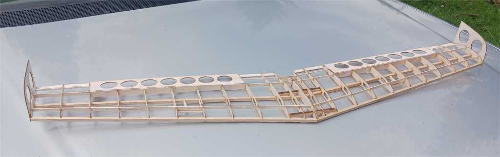
Aeroscout Swept Back Wing
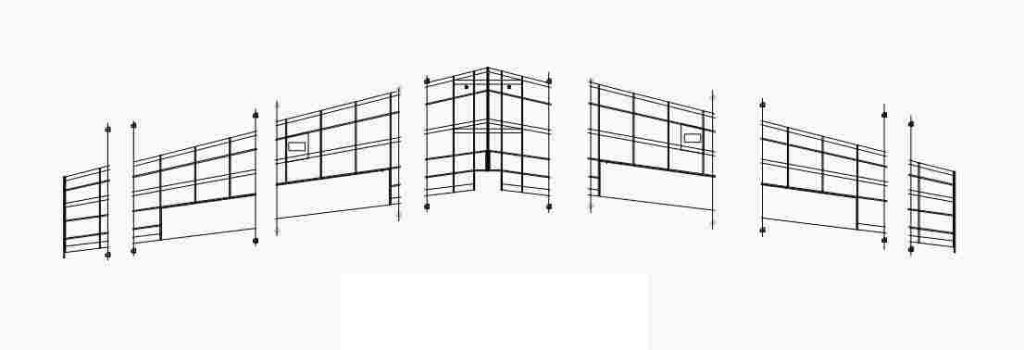
Showing the assembly most of the way complete before adding the center sheet to give you an idea ahead of time along what goes where.
Take note, the current kit’s ailerons are different then the original.
Assembly is pretty straight forward, test fit everything before gluing in place.
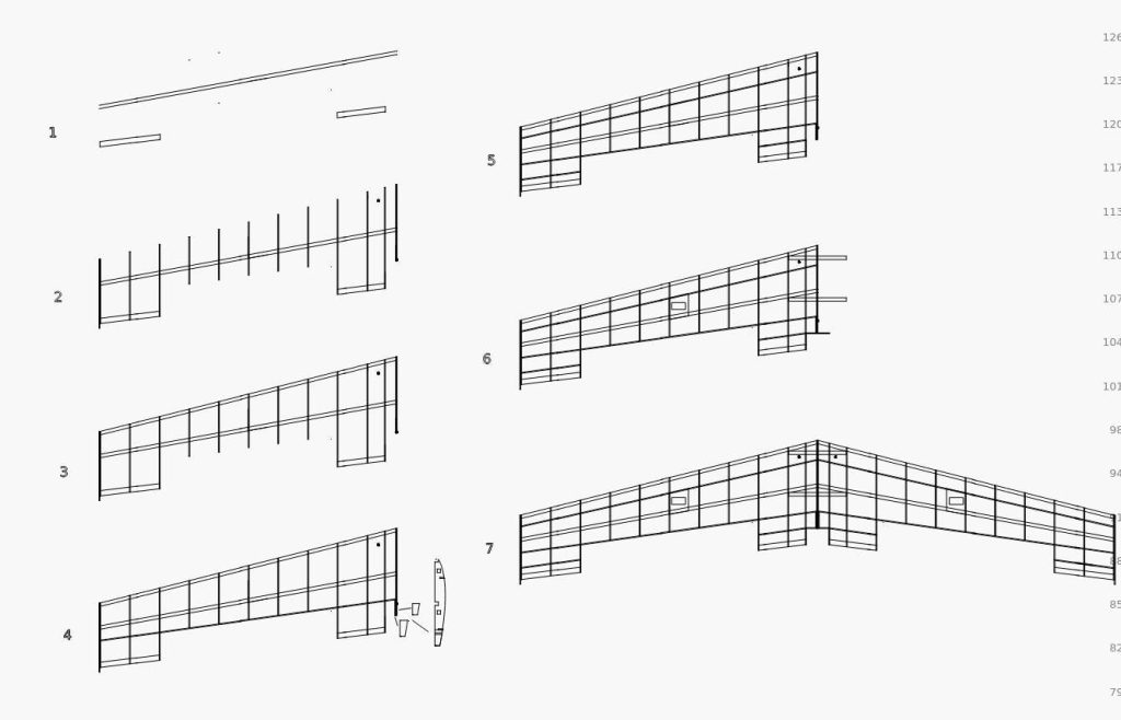
- Pin down the lower spar and trailing edge sections.
- Fit the ribs into place.
- Fit the leading edge piece and glue the ribs to the trailing edge and lower spar.
- Glue the aileron pocket area and adjacent upper spars. Add the extension stock for the center rib for the mounting bolt opening.
- Glue the upper spar and leading edge.
- Fit the center cross-members glue aileron servo plate.
- After right side of wing is complete, test fit and fine tune the cross-members before gluing and joining the halves.
Adding extra stock such as the aileron openings and additional spars are a good option to utilize, the overall weight from the original comes in around 40% lighter then the stock Aeroscout wing so you have plenty of breathing room to be creative about it. Adding the sheeting is pretty straight forward, I prefer to simply soak it in warm water for a few hours, heat it up in the microwave and work it with the iron over the intended area to train the stock to conform before committing to gluing in place. There are several methods to apply it as well. Fill in between the center ribs and the ones next to it, for the best fit on the fuselage.
The opening/lightening holes are to be filled in with the stock at a cross grain pattern, shown on the main page for the Aeroscout wings.
*In addition, an upper center 1/4″ main-spar can be added and is slated for the next generation of kits being cut now.
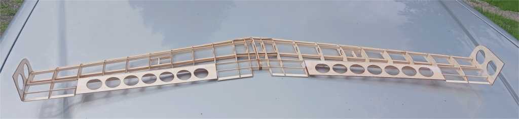
Aeroscout Slow Flyer Wing
The Aeroscout Slow Flyer wing is similar to the swept back version in some basic ways, reviewing it along with the diagram and instructions will be helpful.
Begin framing out the wing, with the lower spar and trailing edge pinned down upon the plans. Inspect the ribs to insure they are in the right placement, in particular the ones that have an opening for the servo leads along with the root ribs where the dihedral is set.
Do not glue in the rib that connects the section together, until they are positioned and aligned up. You will be using longer stock where they join at in the middle for the spars in general to interlock and glue in place first. Take note of the dihedral braces along with how they integrate with the ribs and leading edge.
Align the sheeting and thin ply mounting plates with the intended screws or bolts on the Aeroscout wing saddle prior to gluing in place. Add additional mounting stock stringers for the servo plates.
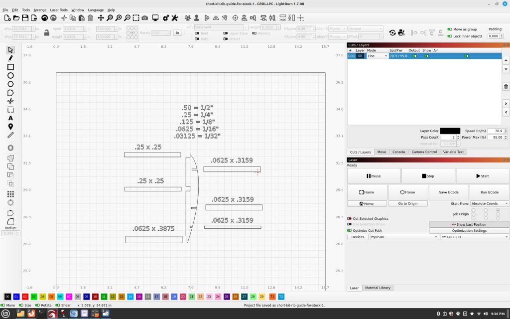
Some additional information for those building the short kit versions. Taking the measurements both from the plans as well as the ribs will determine the strip widths, sizes and lengths.
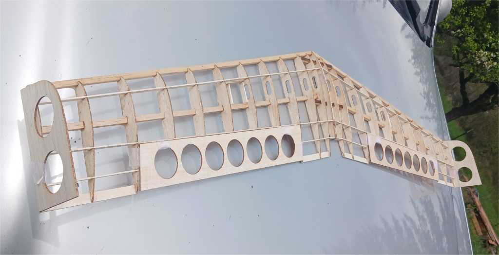
Aeroscout Stunt Wing
The folder for the build photo’s were done up from a customer who had some degree of variations upon how he went about it and work quite well upon. He did an outstanding job overall and his revisions are valid to incorporate if the builder chooses, the folder is browsable. Happyrcflyer.com/Stunt-Wing
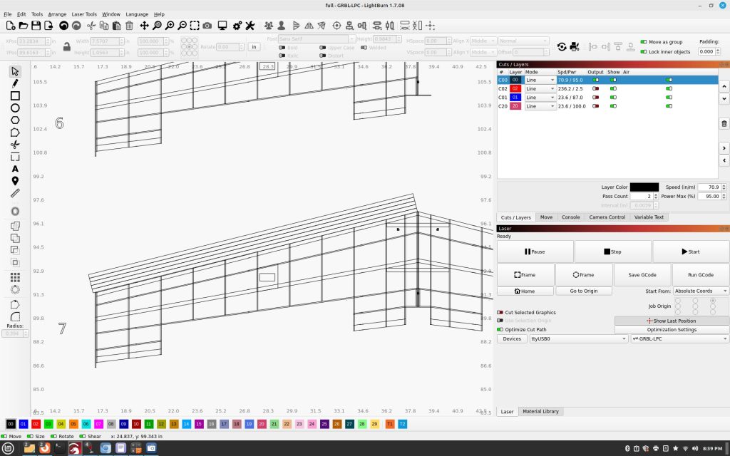
The diagrams taken from the laser cutter files are meant for general direction screen shots of, having the kit parts on hand will be easier to follow. There are a few elements such as doubling up the reinforcement stock for the center main spars and the rest not shown just for simplicity sake for example. The same goes for the ribs on the very end/tip of the wing which are doubled up, not shown in the diagrams.
Joining main 1/4″ spars, there will be three, not just two shown. Also, center rib assembly.
Additional stock added, take note in this case compared to the build photo’s, the 1/8″ aileron opening area/seat stock is a separate piece.
Make sure to align the forward sheeting to wrap around the leading edge of the wing, original file upload on the build photo’s folder shows an alternative manner going the other direction which also works. Take note of the cut out’s on the ailerons, remove, and put them back into place cross grained to prevent from warping over time.
Set the center of gravity on the Stunt Wing 25% back from the leading edge which comes out to 2 inches. With all of the new wings, use some foam board strips to shim where the wing mounts since it’s not the exact same profile as the original Aeroscout wing, one doesn’t need to put in anything special for that aspect.