This being an intermediate level kit will require some previous balsa building experience while also not requiring the necessity of absolutes in step by step instructions for each individual piece. You will want to review the instructions and photo’s prior to starting. Always know that I am here for support and can be reached through various channels, also, this build guide and instructional can be added onto and supplemented as needed. I’m showing both a diagrammed out format that has some minor revisions recommended but not mandatory and my original format along with to draw upon in the text and photo’s of the build along with below it.
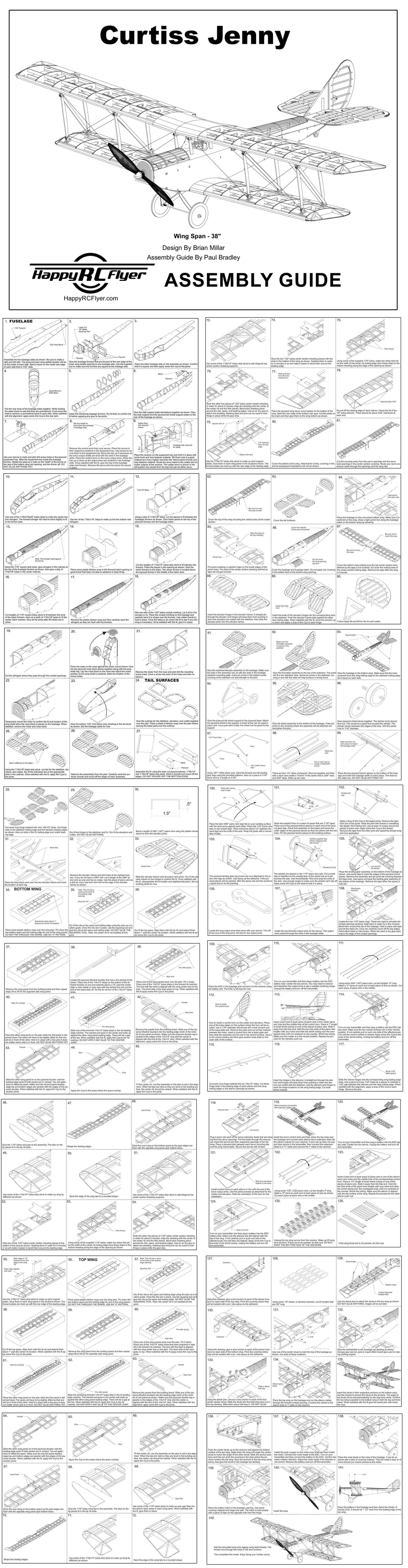
Complete build guide: https://happyrcflyer.com/curtiss-jenny-assembly-guide.pdf and a 1.5 mb Jpeg format: https://happyrcflyer.com/full-curtiss-jenny-build-guide.jpg
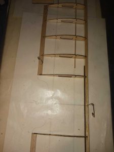
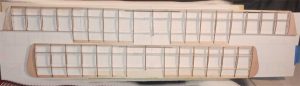
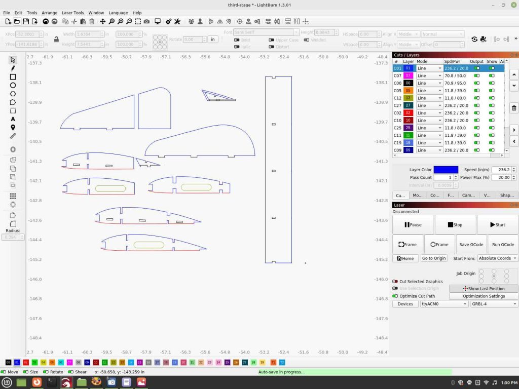
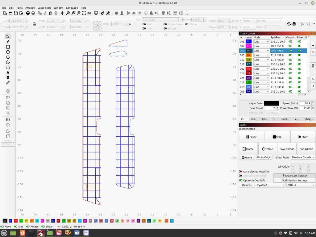
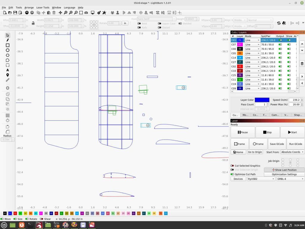
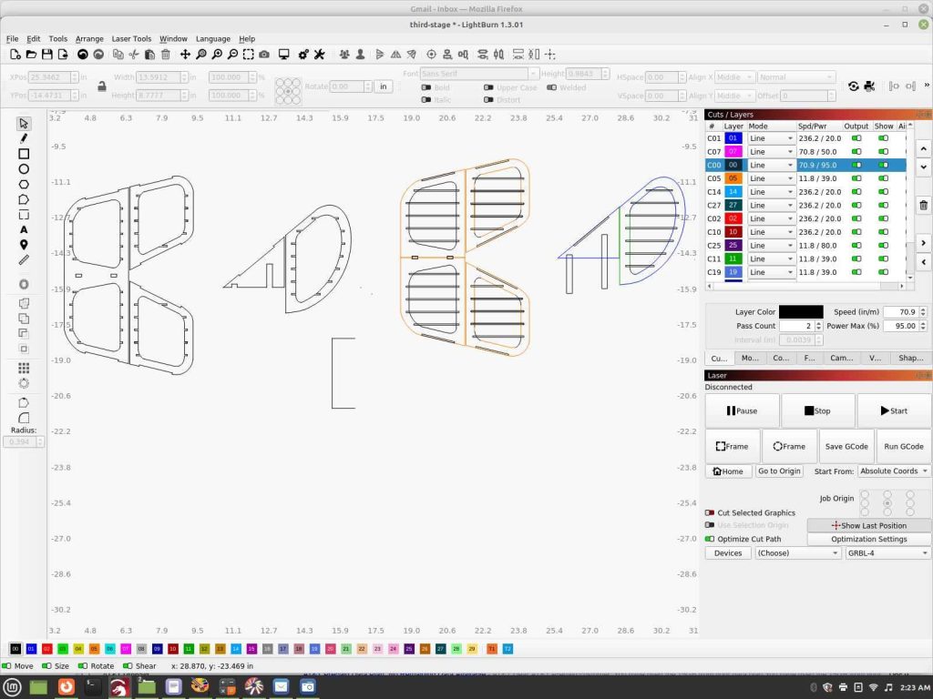
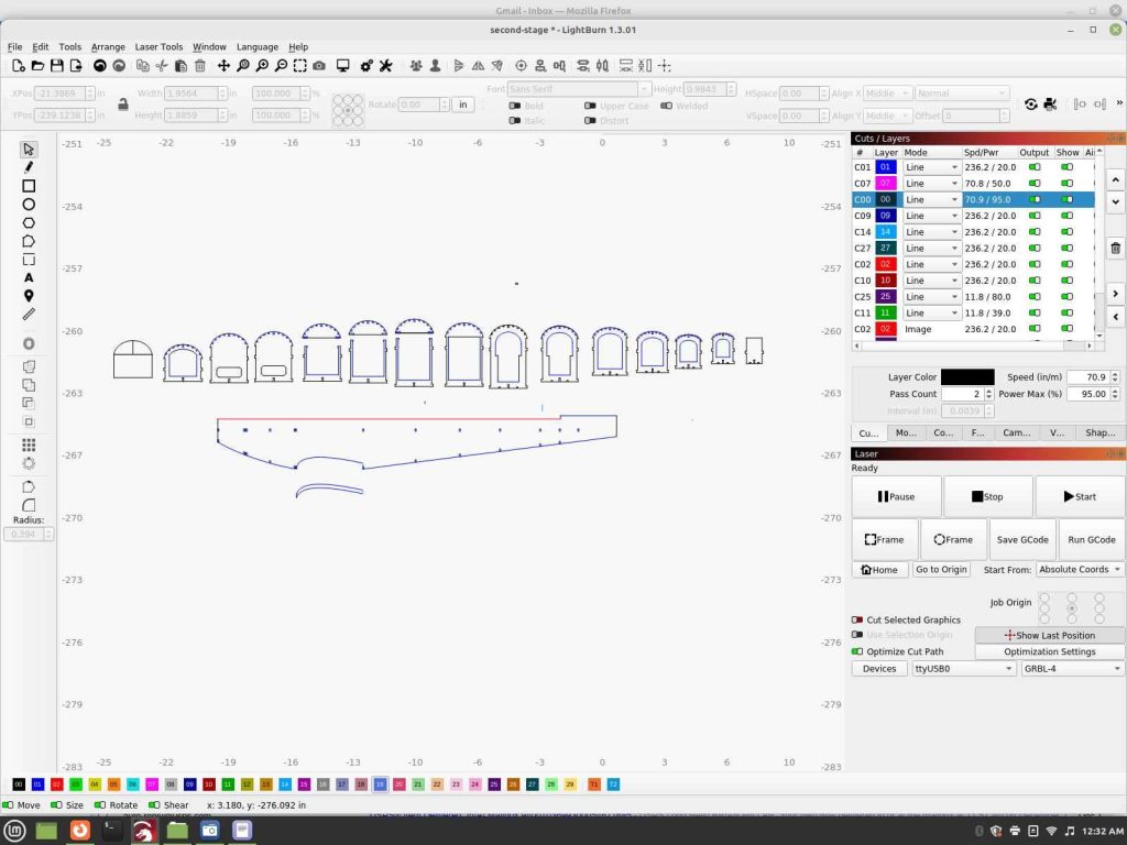
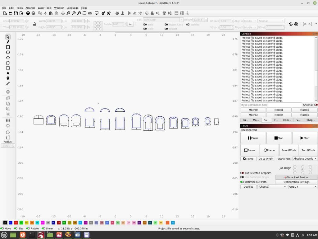
Showing Paul Bradley’s past work in progress screen shot photo’s to give you an idea upon what he’s done to help out, thank you so much Paul! This was a work in progress upon at the time with plenty of his own revisions and suggestions to go along with the basic Jenny kit build on it and the final build guide he put together.
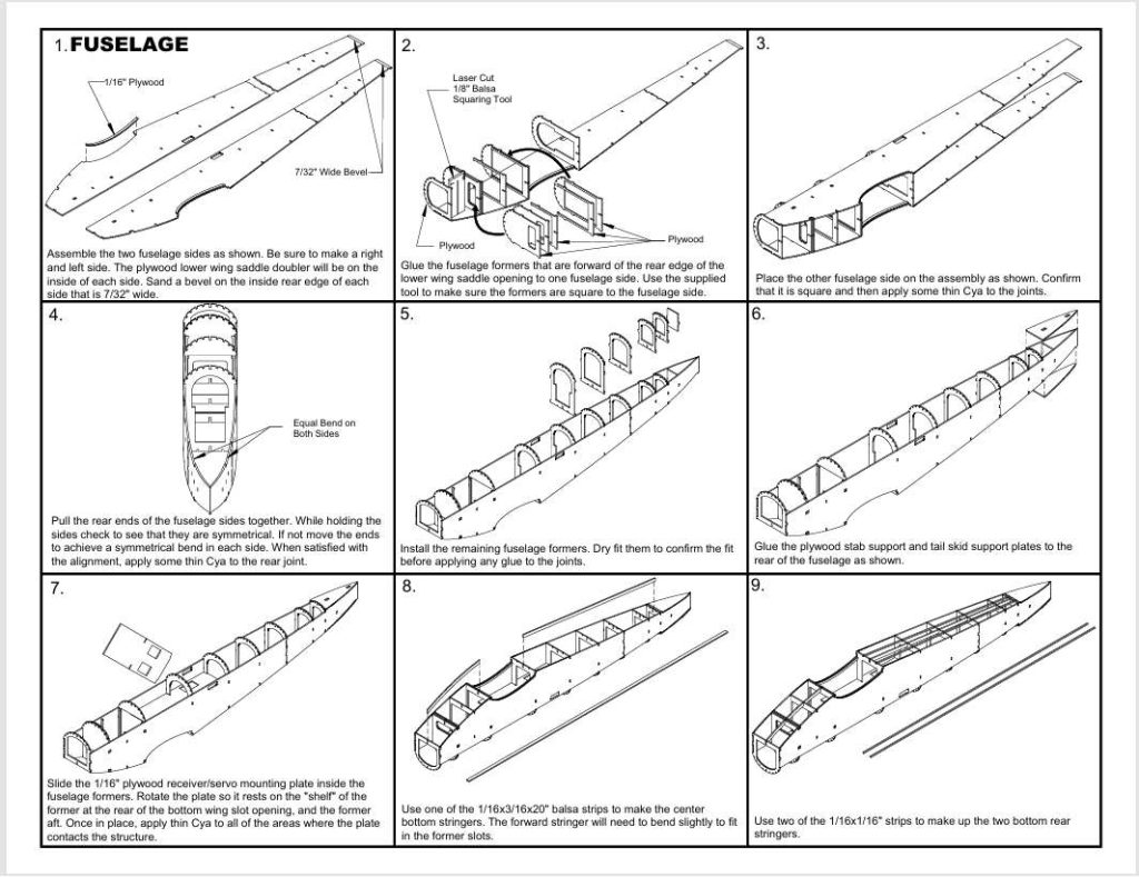
I do recommend for the average builder to put in all of the formers on one side before connecting the two halves together so keep this in mind with frame 4 and 5 upon. Advanced builders may find adding them into it after the halves have been joined a challenge but may make the process easier for them along assembly too.
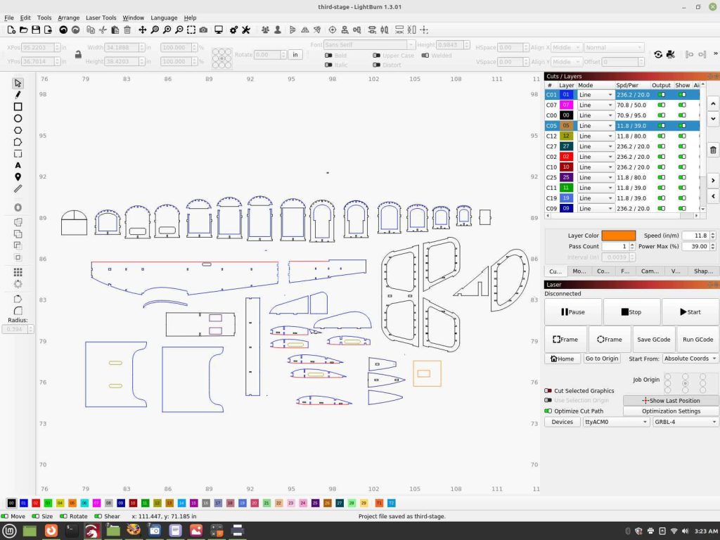
The second stage along instructions are implemented in a photo series only with text to fill in afterwards, moving this into additional details and instructions.
This format is based upon the original intention with full length ailerons, it was deemed impractical for many reasons to implement, a minor deviation from the original, full scale Curtiss Jenny. Take this into account along the progressed photo’s as the build continues and as you are building yours with the cut away from the wing only format. The Slow Stick Cub is a great similar wing design example to reference upon with it’s build guide for the ailerons on the Jenny.
The photo’s shared are from the original prototype, so things such the ailerons were revised afterwards and are designed into the production kit. They are helpful for the build along with, be sure to check out what is going to be shared on it’s smaller, 26″ wingspan version which is based upon it for this format.
Basic text instructions with the photo’s below them are as follows.
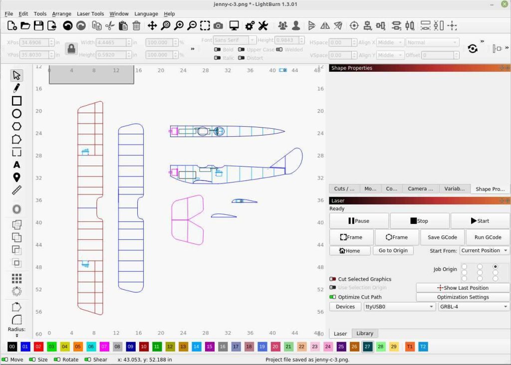
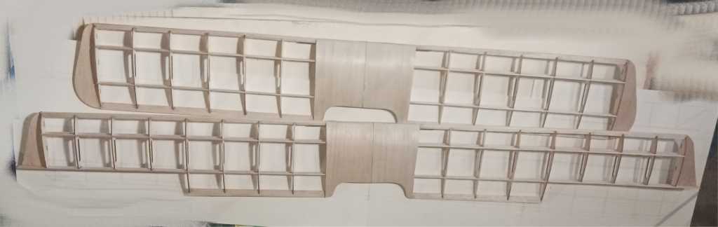
Wings:
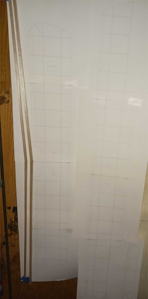
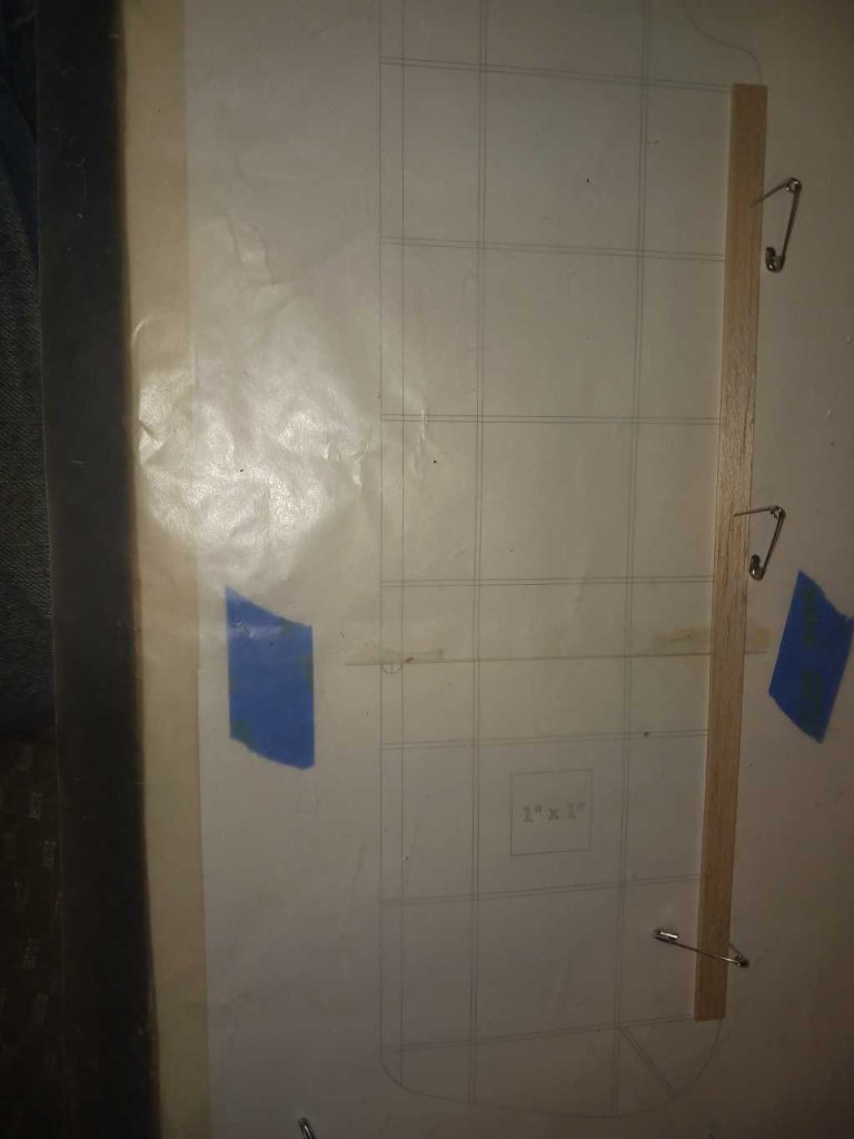
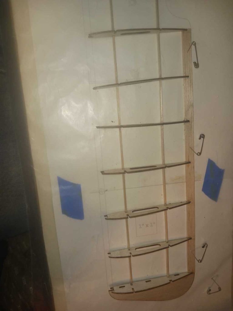
The wing-plan sheets will need to be cut and taped together, with T labeled as the top wing plan and the B labeled for the bottom wing. The original intent was having the ailerons to extend to the top of the wing, which can still be done with some retrofitting, the kit was revised to have them cut into the wing making it a simpler process to assemble.
The wing-plans can be downloaded and printed at happyrcflyer.com/Jenny-wing-plans
They are supplied printed out already in the full kits that are ordered. It also would be inspirational to those riding the fence along ordering one or just are dreaming of it type of thing to download, print out and assemble the wing-plans just for inspiration upon.
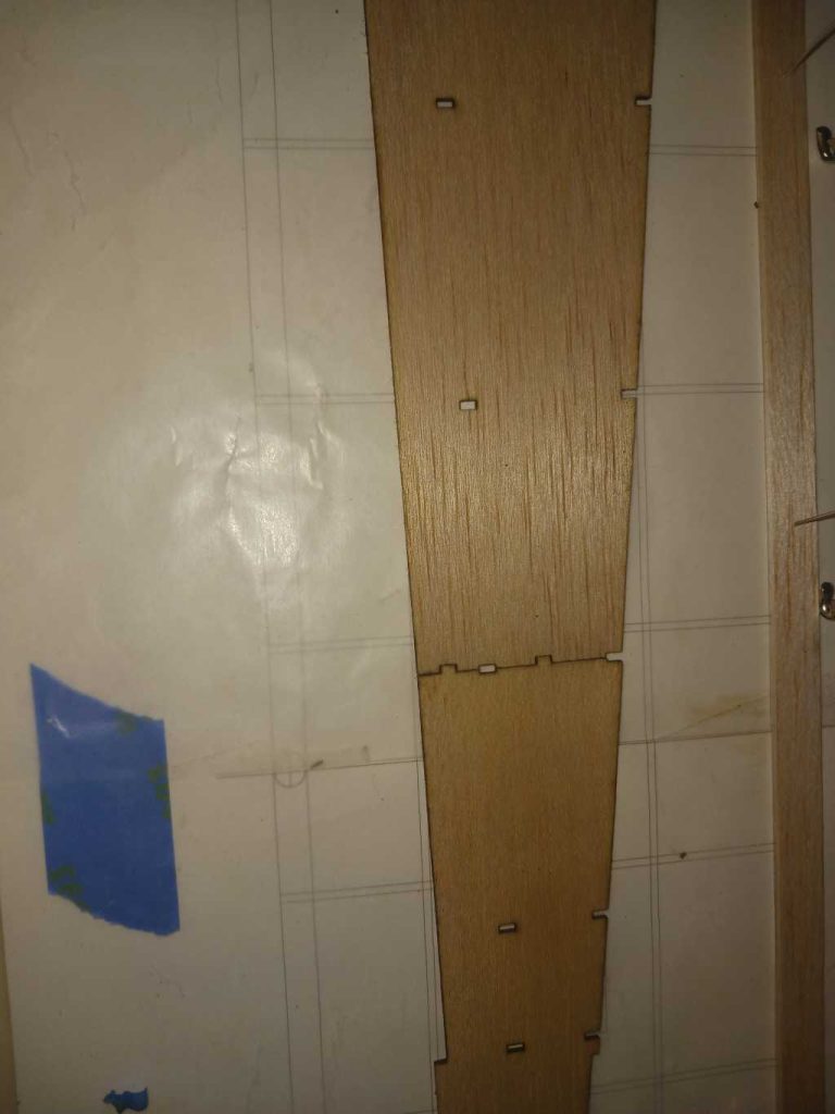
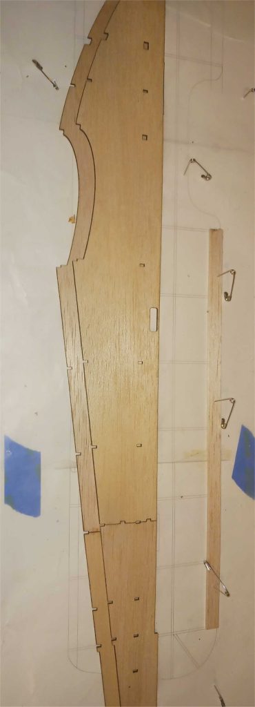
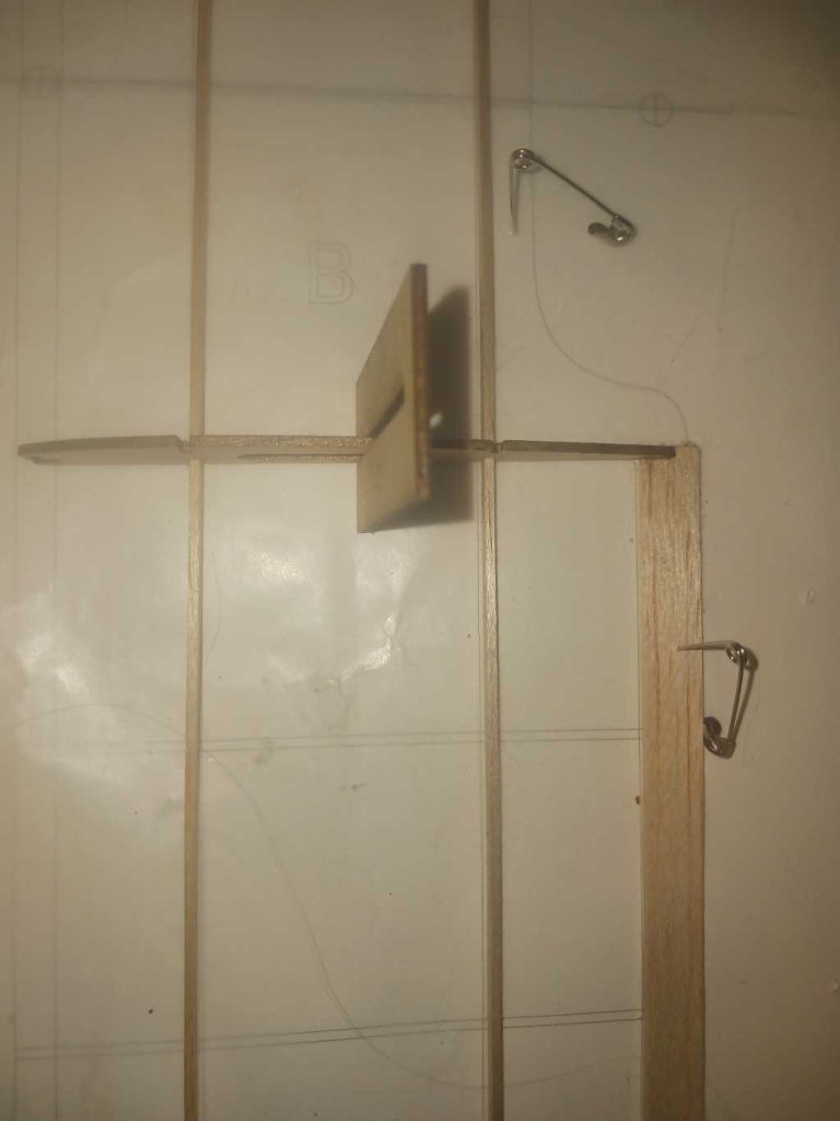
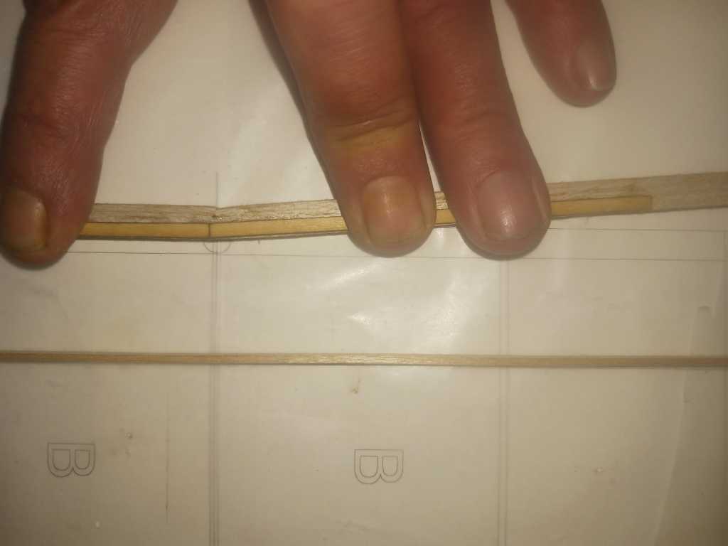
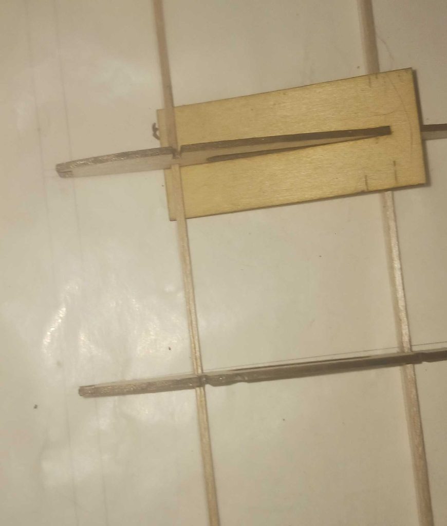
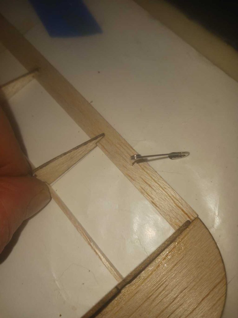
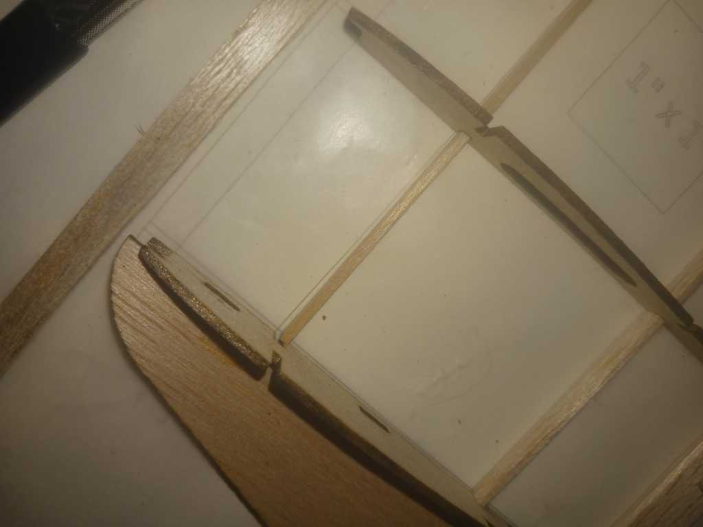
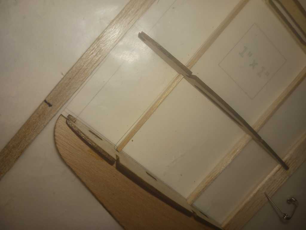
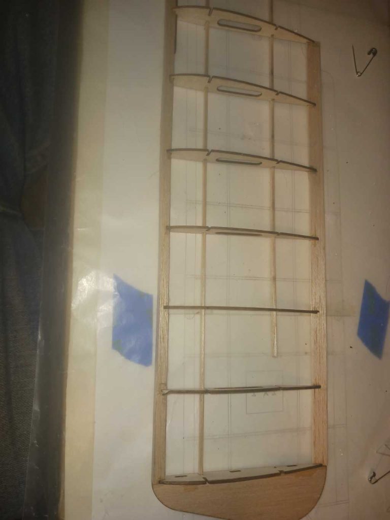
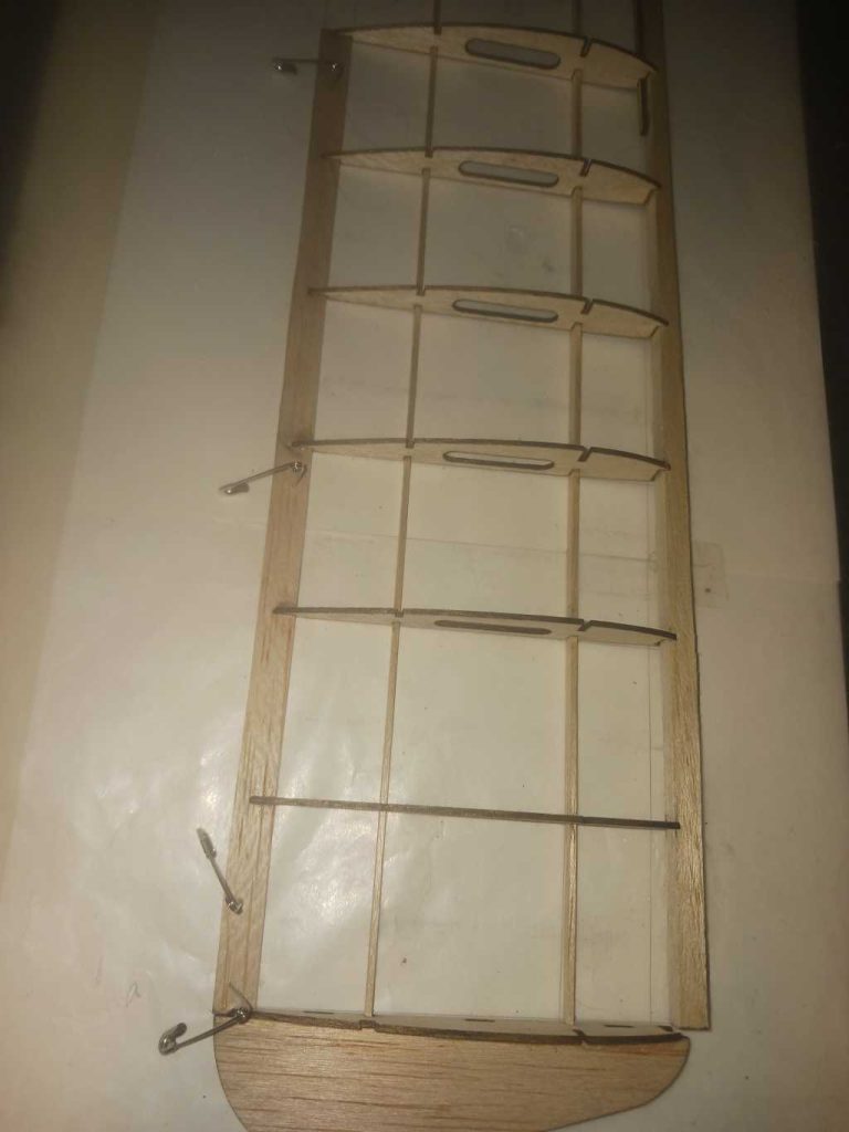
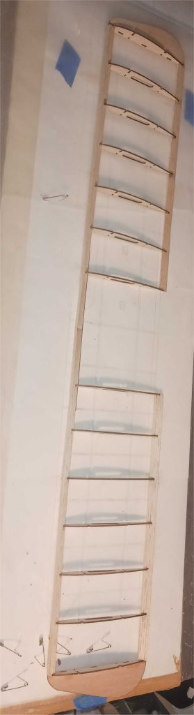
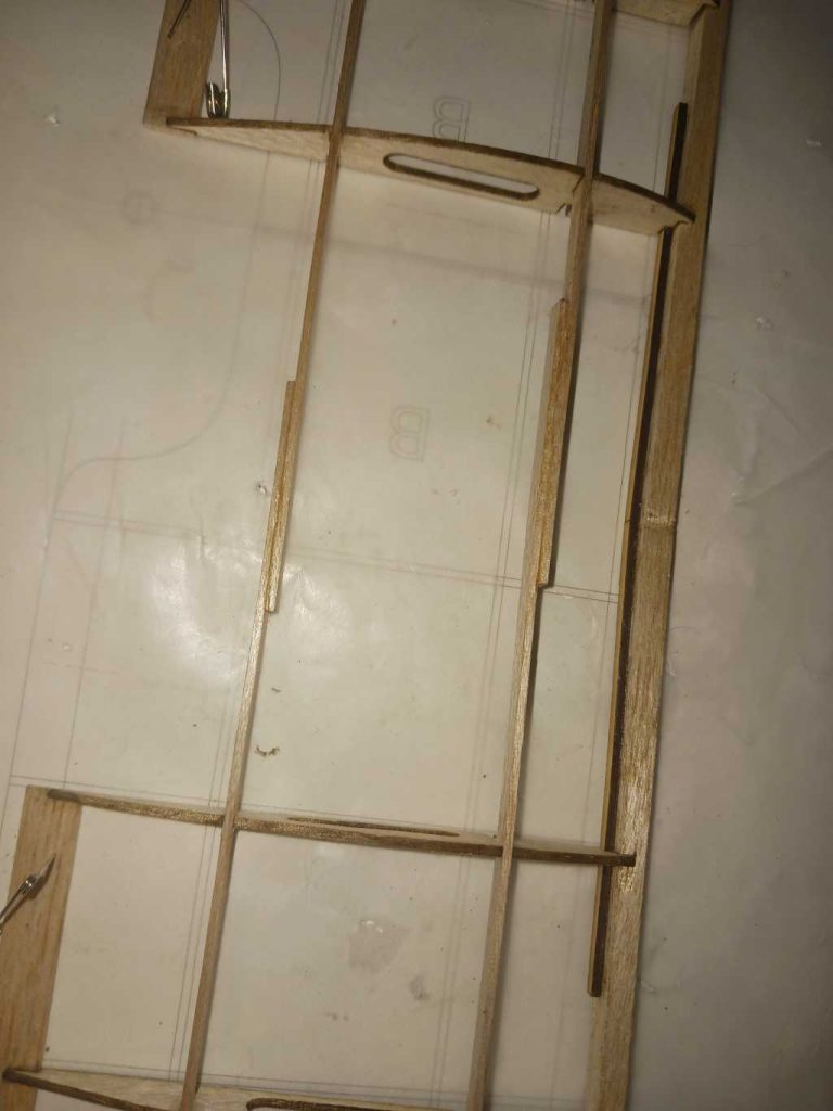
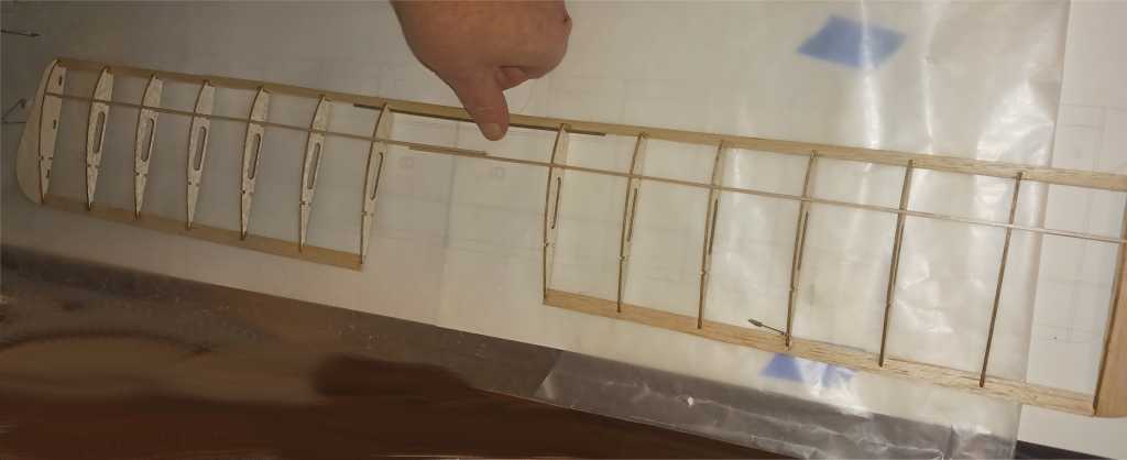
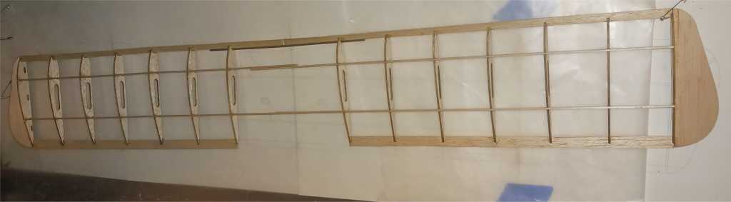
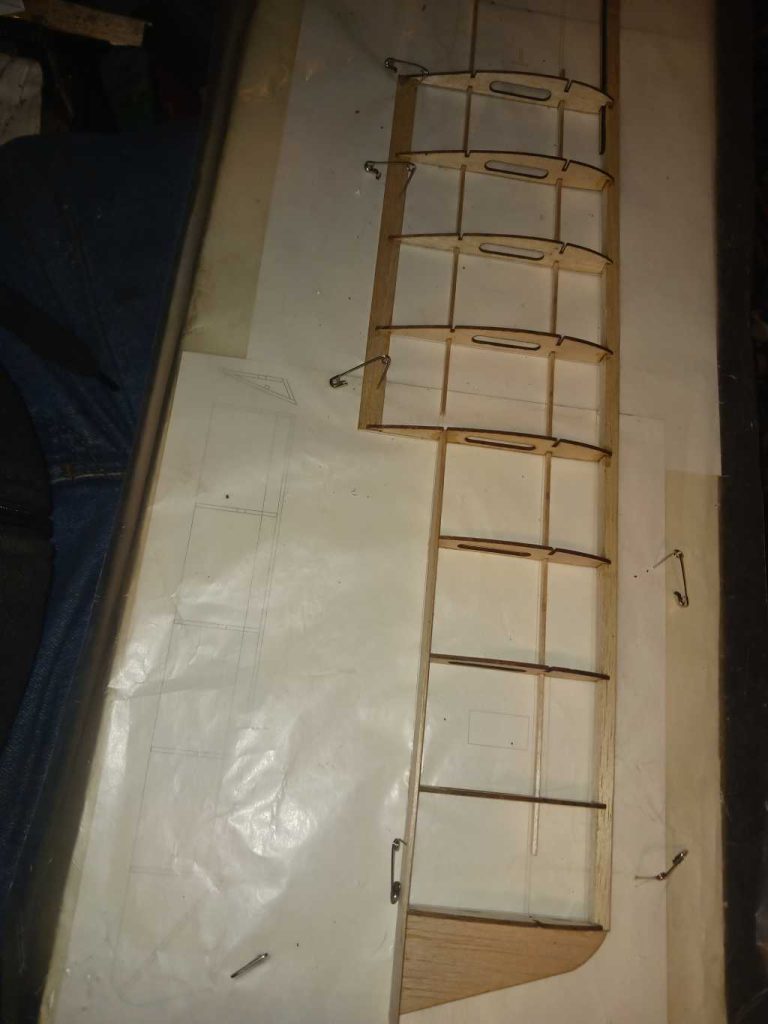
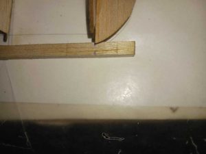
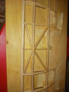
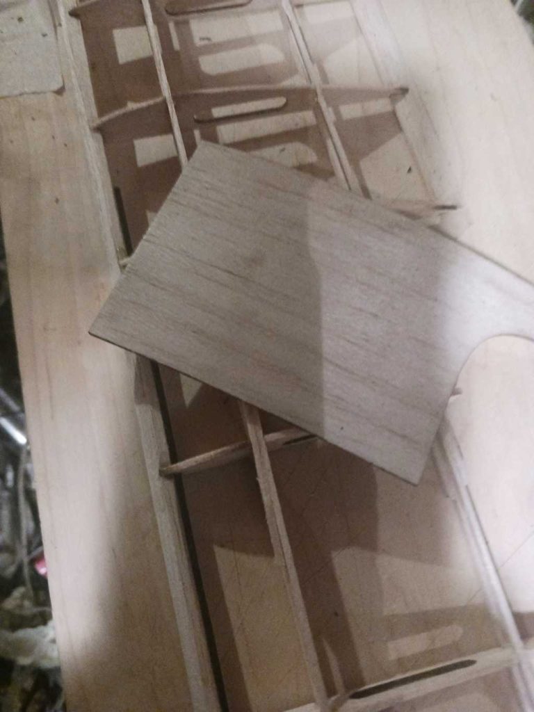
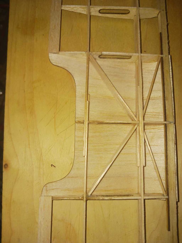
Take note when placing the ribs which ones correspond to the servo holes, having a cut away which will make the servo tray’s flush with the bottom of the wing, the same with the servo wire trays being of the same. You will be doing each side of the wing and joining together with the light ply dihedral brace on the leading edge stock, tying in the top spars to join together along with before moving onto the bottom spars afterwards. From the stock lengths add the strut mount sections between the ribs.
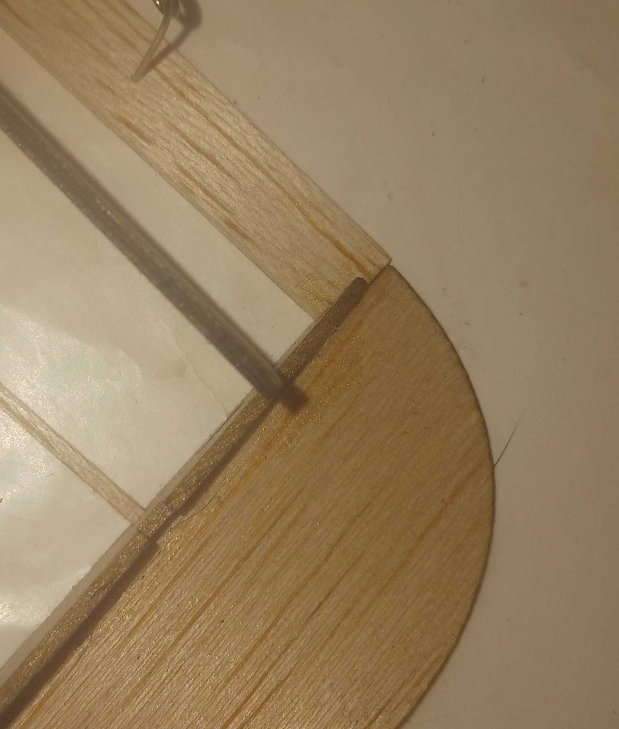
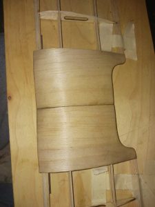
Soaking the center sheeting is necessary to wrap around the frame, take note of the orientation of the cuts where they join.
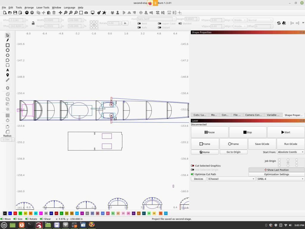
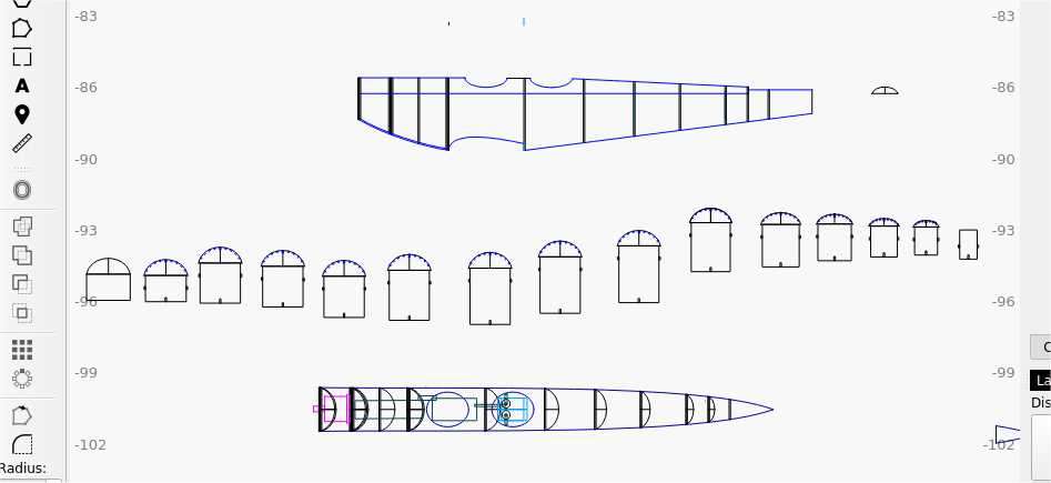
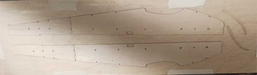
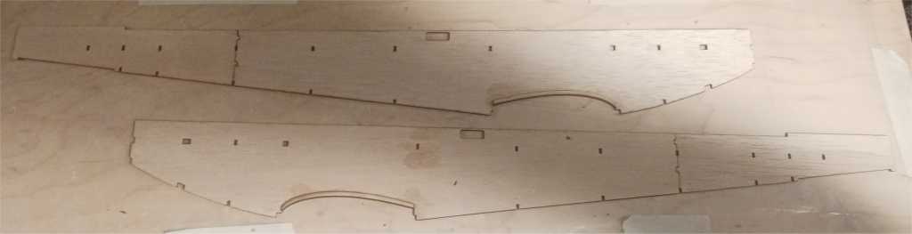
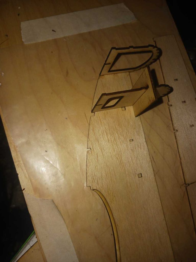
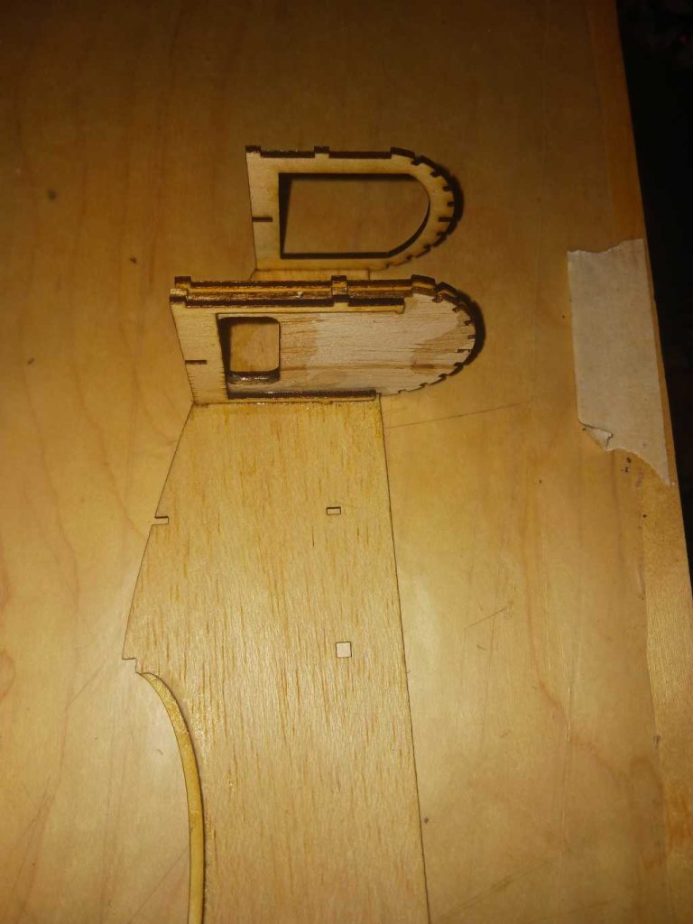
The Fuselage:
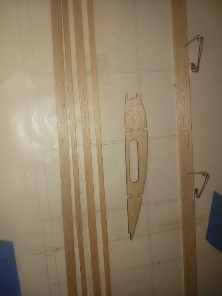
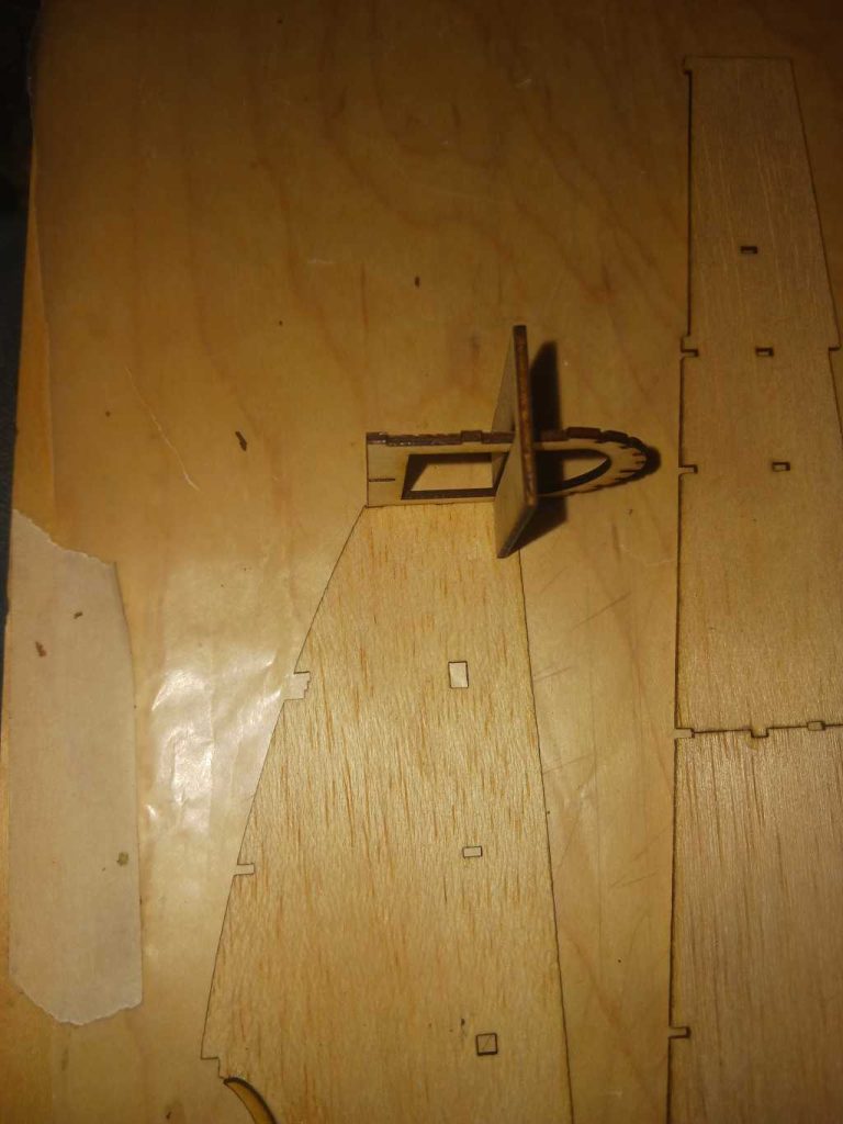
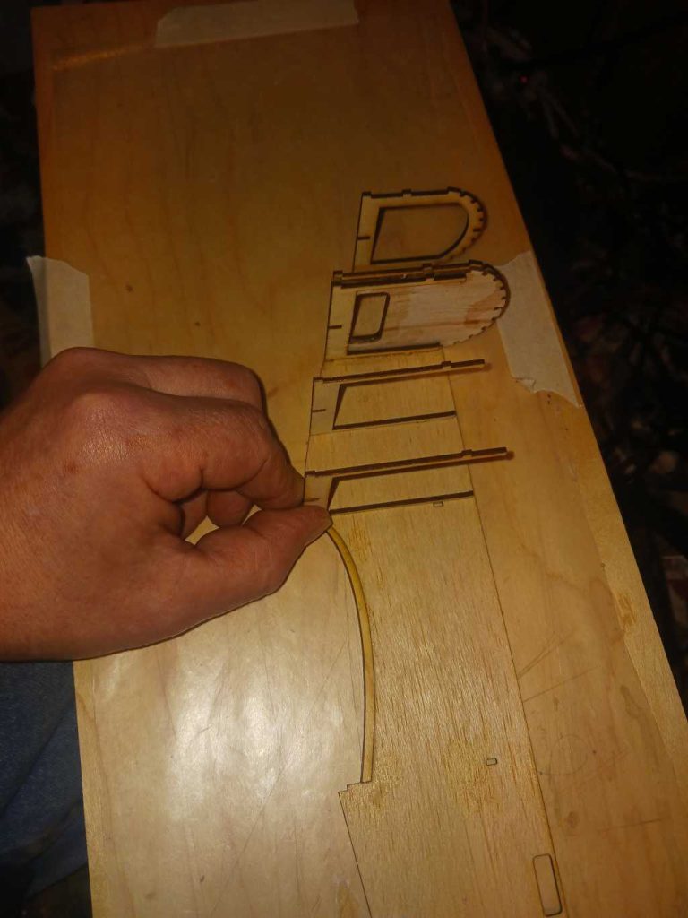
Join and glue the sheet halves for each side and position in order the former’s. Each former has it’s own tab and slot to fit into, glue them in place on one side, then join the second half sheet together. The servo tray also can be added before join the halves by resting in place and applying some thin CA to adhere where it’s touching the formers and the rest. Take note along the tail sheeting stock which will also help to line it up square when joining the tail tip. Add the thin ply lower wing brace sections to the inside of the sheeting.
From here, add the stringers, soak and glue in place the cockpit sheeting. The engravings shows where the openings are which are cut out along with through the stringer stock that’s underneath the openings. You can wait until later to cut the openings upon after you cover the plane and apply the cockpit opening rims.
The battery hatch area is using the three former’s, with the respective stock cut to length supplied in the kit to align and space them correctly. Use the extra stock supplied for supplementing the hatch before drilling through for the dowel stock to secure it in place for flight.
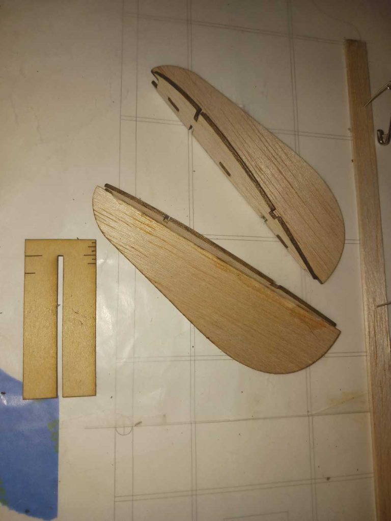
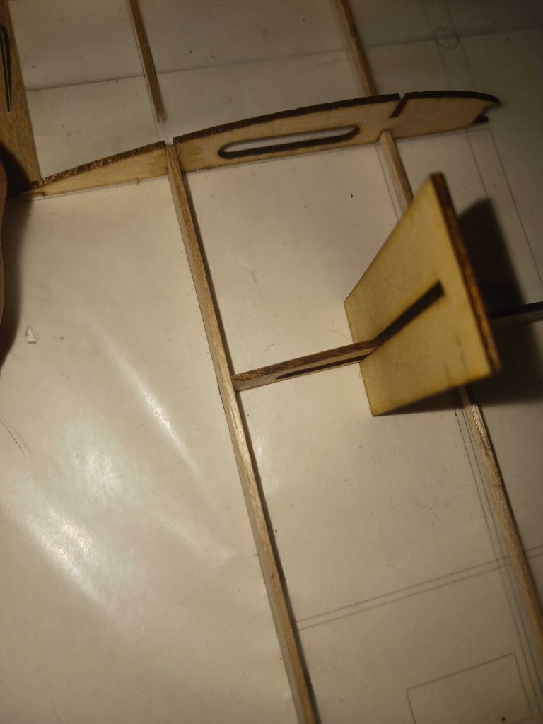
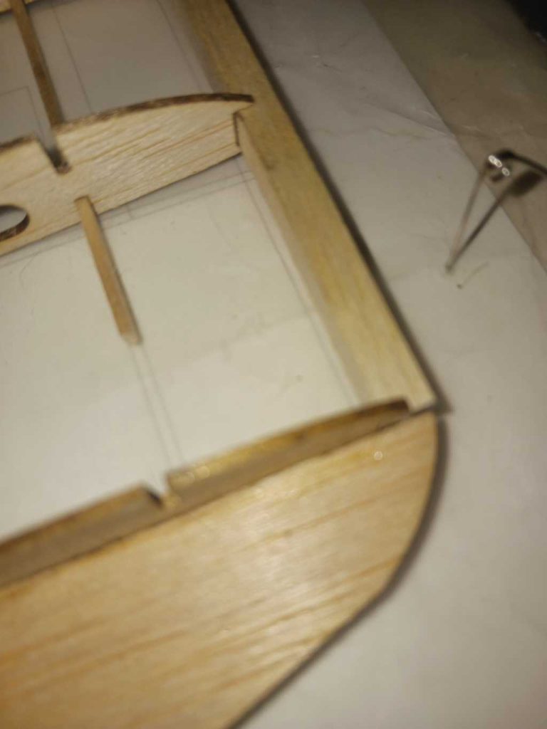
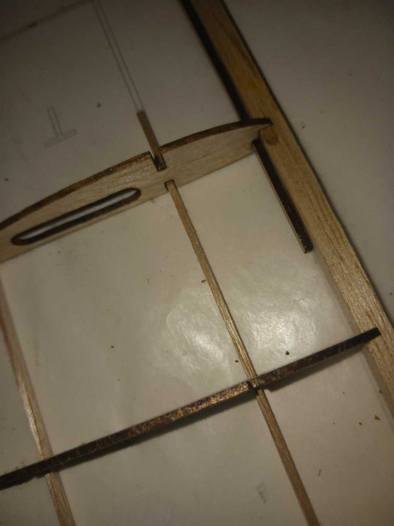
Elevator and rudder:
Assemble the elevator and rudder from the 1/8″ stock and fill in the stringers.
After covering the parts:
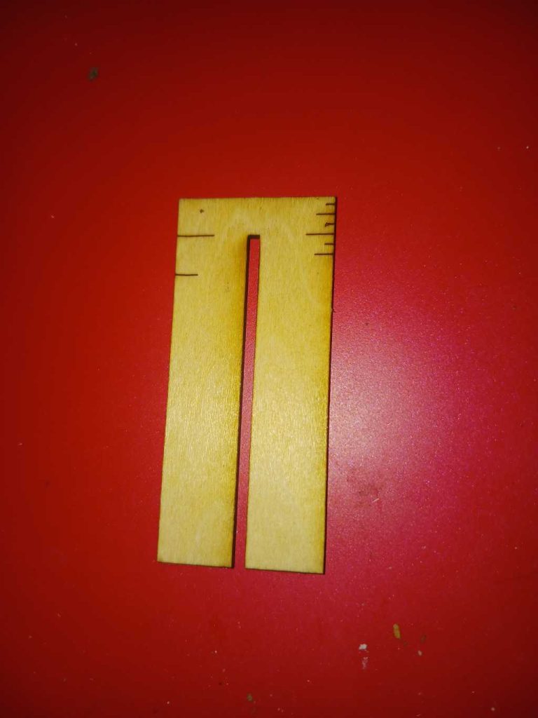
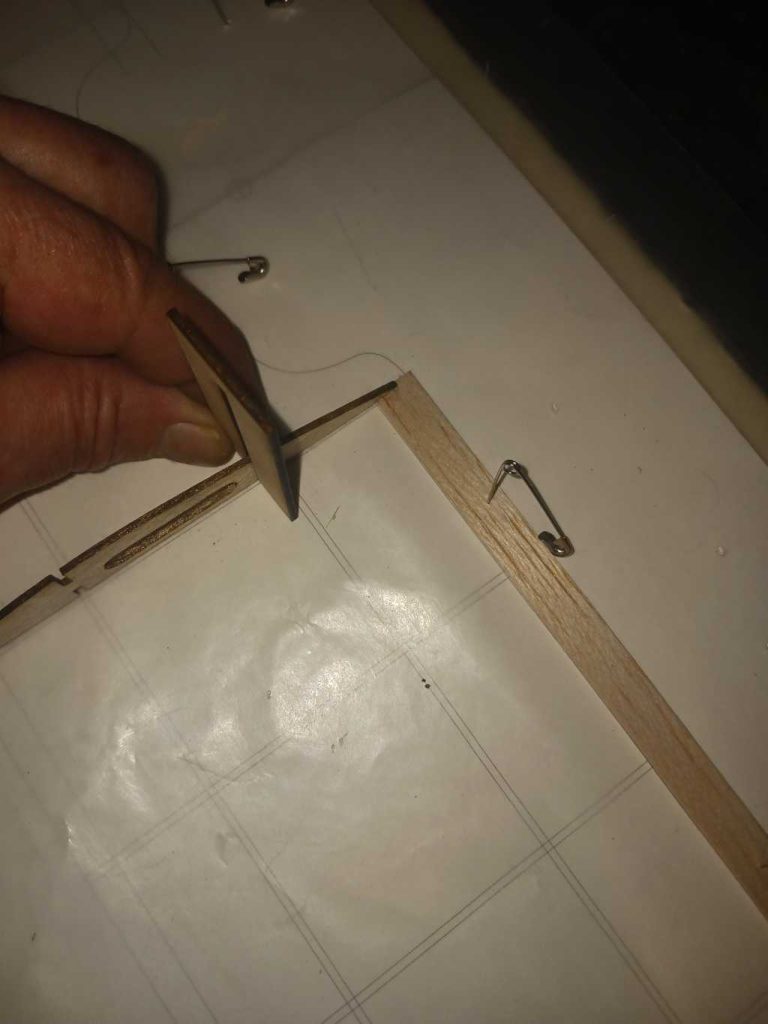
Assemble the strut mount clips. Alignment will be as follows.
Assemble the front grill, this is only placed after installing the motor. Using tape or clear Doculam covering, secure it in place.
The electronics, connections and the rest are pretty standard and no need to elaborate upon further unless requested. Some carving and the rest will be needed based upon how you mount the motor, with the battery hatch but other then that, not a lot of customization is necessary.
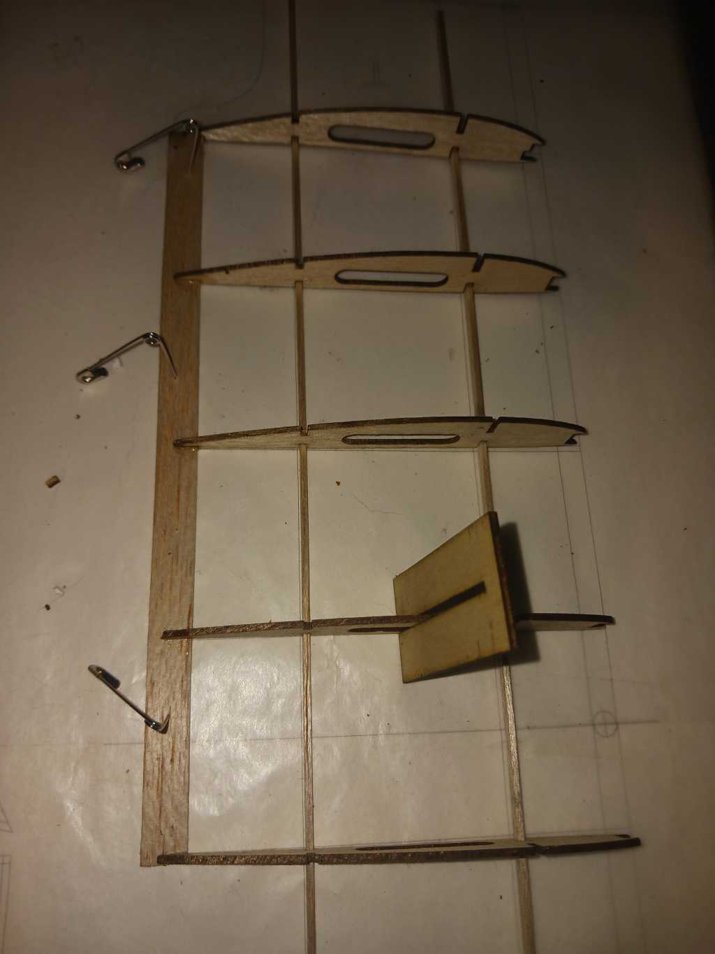
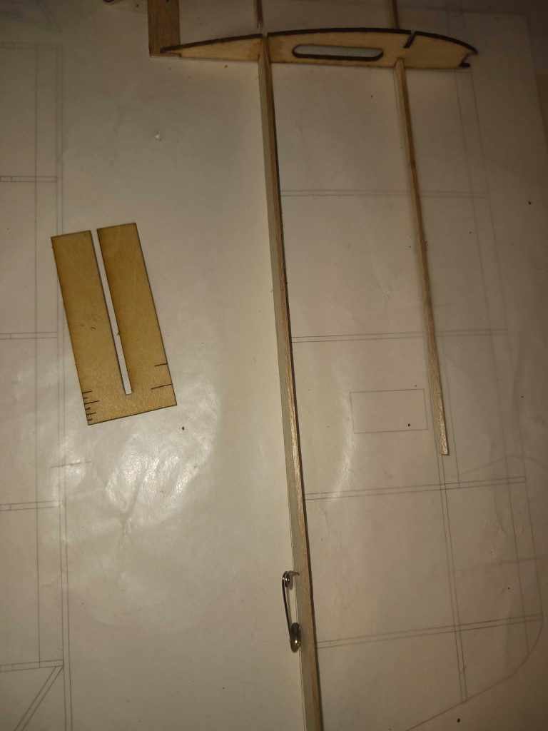
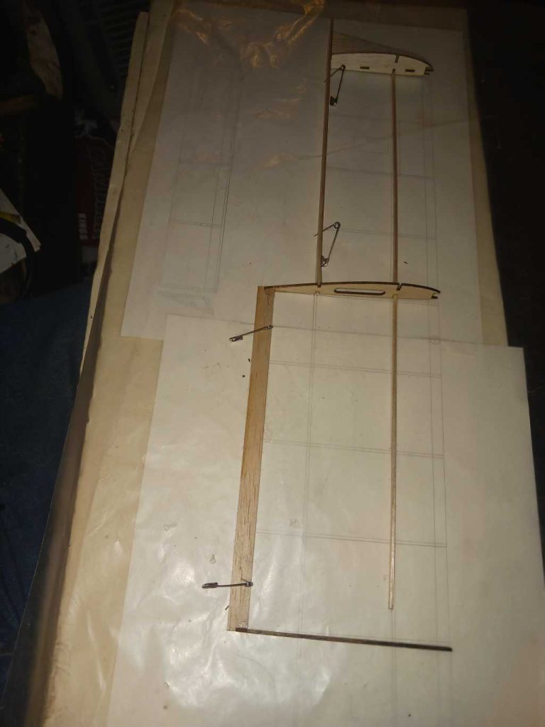
Landing Gear assembly:
Bend the the piano wire of choice using the pattern1/16″+ recommended, it will take a second bend for the proper angle from there, then adding the axle to complete the frame. The stock in the kit supplied in small strips will be used for it’s mounting spot area, along with the side rail strips. Mount the washers and wheel stock from there.


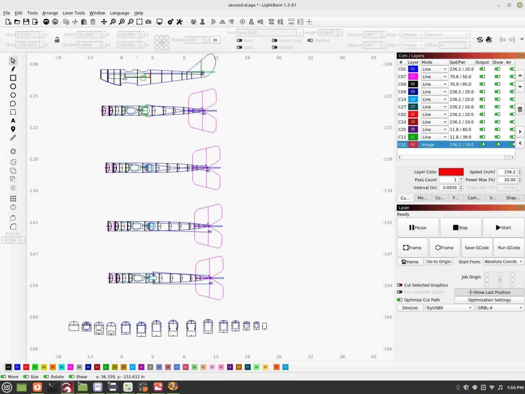
I am going back to diagram format for the rest of the build for now, it’s a long story behind that, these photos are helpful along continuing the build.
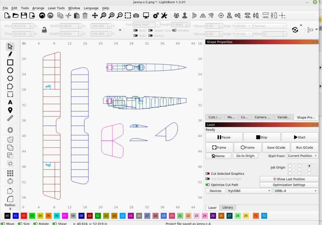
Showing the variations for the tail feather and servo controls upon.