It’s recommended for newer or first time builders to stick with regular wood glue or what is commonly called PVA. CA/Super glue is a much faster route to go for those experienced using it for most of the assembly and a combination can also be used.
The Wing
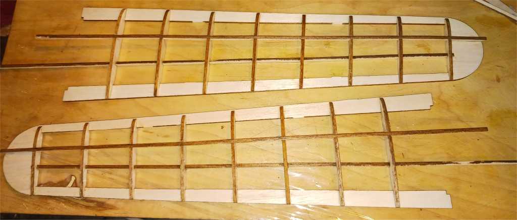
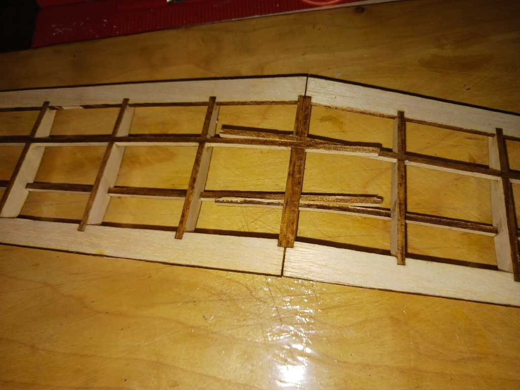
Lay down the wing halves, remove inner alignment crossmembers, test fit and glue in the ribs. The center/root ribs are glued together, and not to be glued onto the framework as of yet. You will note the center ribs have larger cut out’s in them.
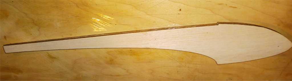
*Note, the one piece wing sections are phased out so you will be required to glue together the additional sections to form one piece again as shown in the original format in the instructions.

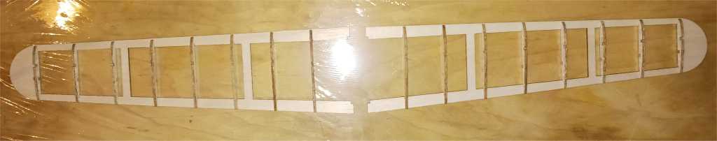
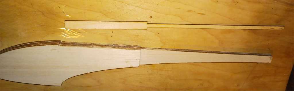
Add the top spars.

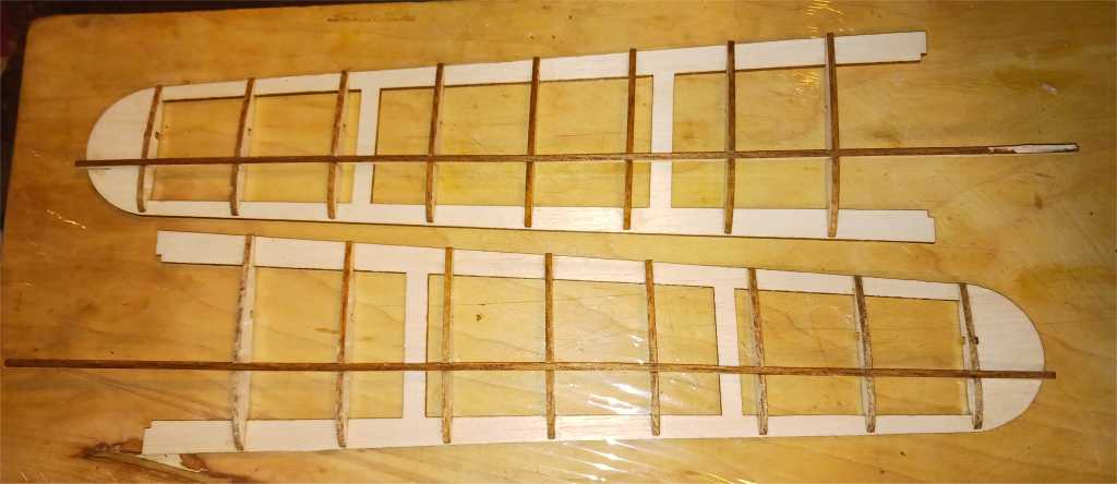
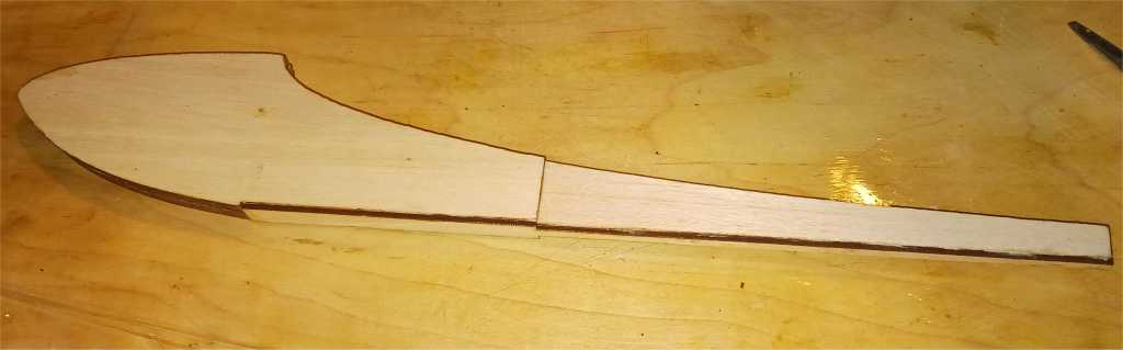
Cut away the temporary joining stock which kept the wing pattern in lined up. Glue the spar onto the tip of the wing, bending it slightly in the process.
Add the bottom spars.
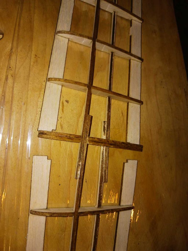
Place the center rib into one of the wing halves. Do not glue in place yet.

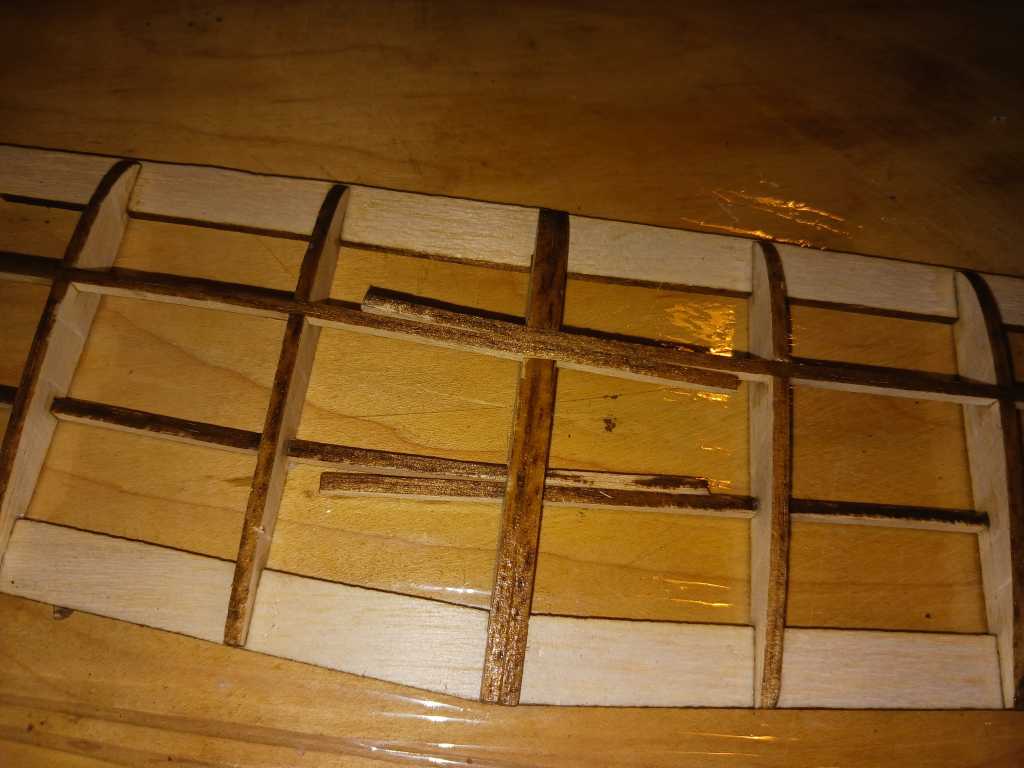
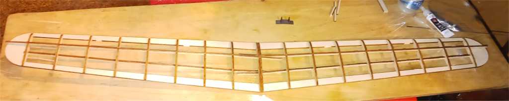
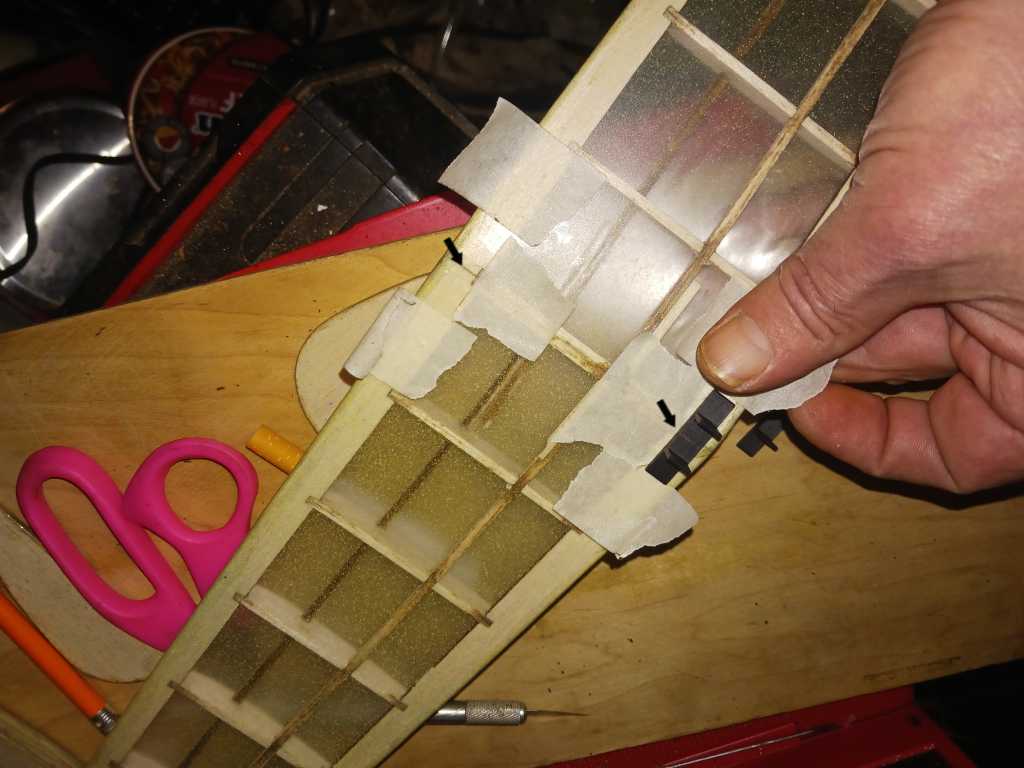
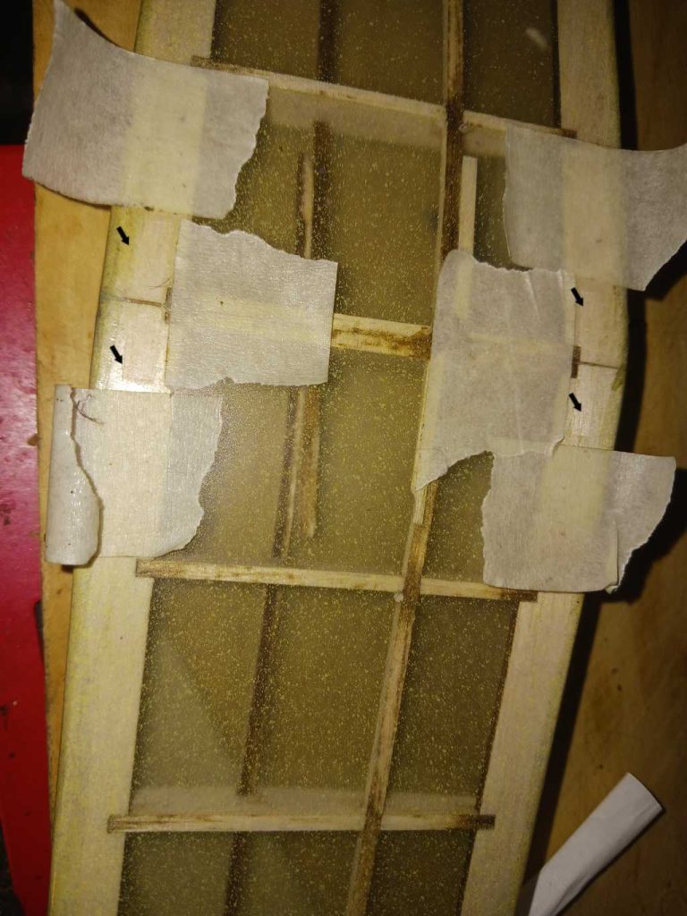
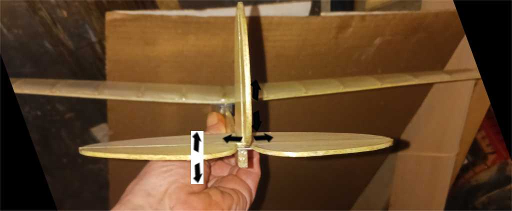
Join both halves together, feeding the spars through the slots in the center rib. Make them align so that they both interlock together. Showing in this case, the lower wing section’s spars are on the inside of the slots.
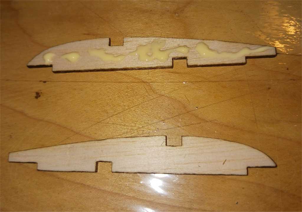
Using masking tape to hold the sections together, use the wing saddle piece to help set the dihedral by using it as a gauge, placing it on top of the taped together area on the bottom of the wing, adding more tape and adjusting it as needed for a temporary hold.
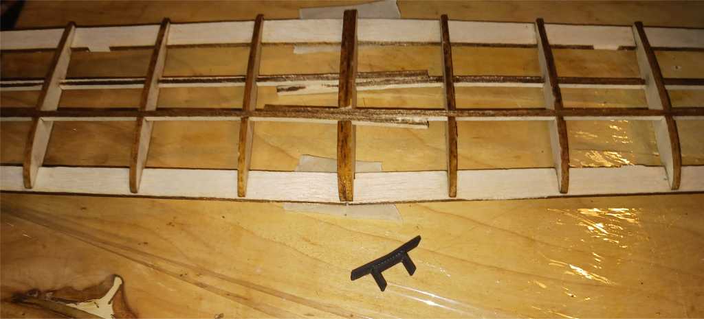
Once comfortable with how it goes together, if you are using just wood glue, you will want to separate the wing section, add the glue to the appropriate spots and place back together. Super thin CA can also be used instead without the need to separate the sections.
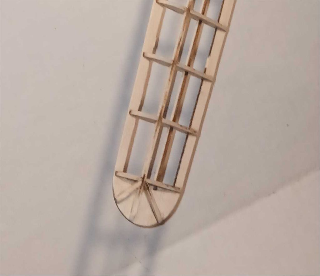
Add the wing tip reinforcement stock as desired.
The fuselage
Glue the main halves, then the side sections.
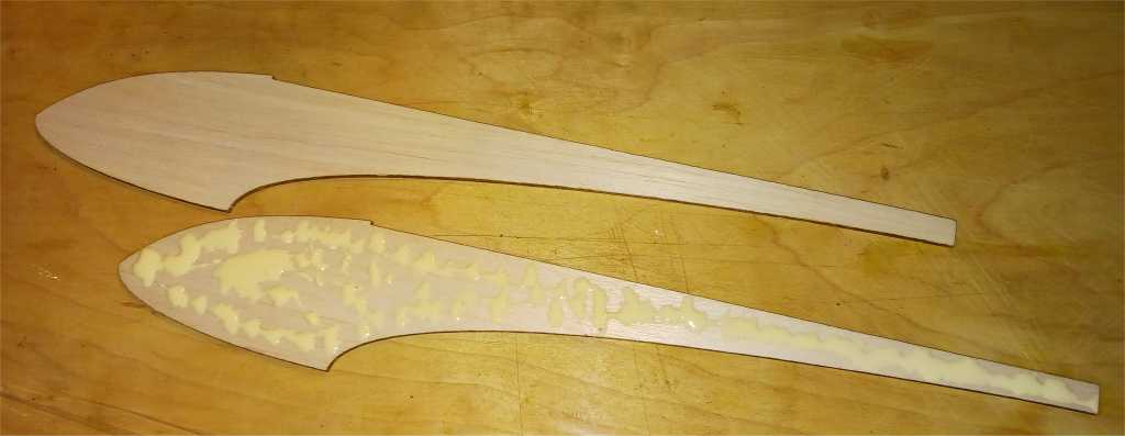

Add the thin ply reinforcement section.
Sand as desired and as needed for the wing saddle pieces to fit around to mount onto the fuselage.
Cover the wing and optionally the fuselage and tail sections. The guide is provided here: https://happyrcflyer.com/covering/
Assembly
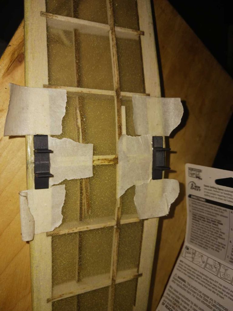
On the wing saddle pieces, mark a line along the center, following the dihedral angle across the front and inside section to aid in visually lining it up. Line up and apply tape on the wing to help with orientation of the wing saddle pieces before cutting away some of the covering to mount them.
It is recommended to use epoxy to glue the wing saddle sections onto the wing, being ASA, wood glue will not adhere to it and CA will technically work, it’s helpful to have the extra working time to line up the sections correctly. It’s also easier to remove the tape once the epoxy is only partially set up/dried.
The process for prepping the wing saddle mounts onto the fuselage is similar. By default the wing incidence is set to neutral, where the front and rear half of the wing are level with the top of the fuselage. You can hold off on epoxying into place if you want to experiment with different incidence by merely taping the wing saddle into place and test gliding the plane after it’s complete to find your preferred angle, epoxy into place from there. It is recommended to hold off on epoxying in place until after the tail is mounted just in case some fine tuning is required to keep everything lined up, square and level.
Showing the rudder and vertical stabilizer sections being hinged with CA hinges, optional, a section of Doculam or tape will also work to hinge the control surfaces.

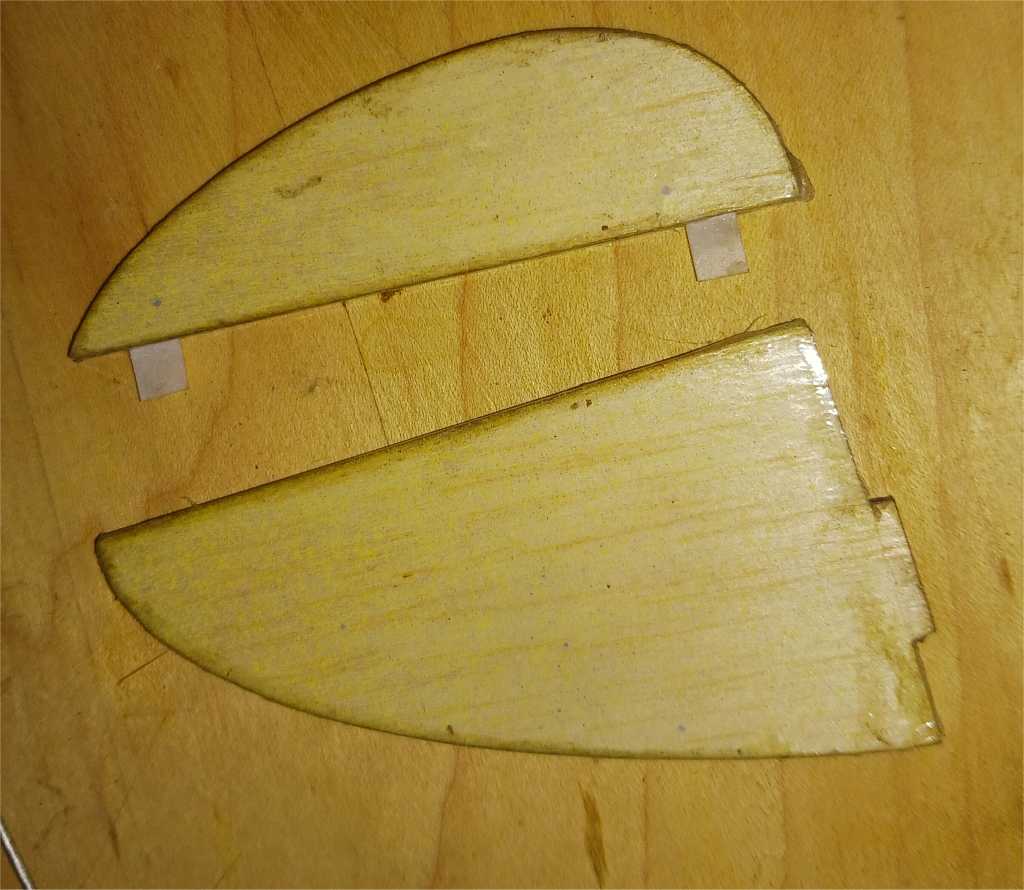
Test fit the stabilizers, and remove covering in the sections where they are to be glued together later.
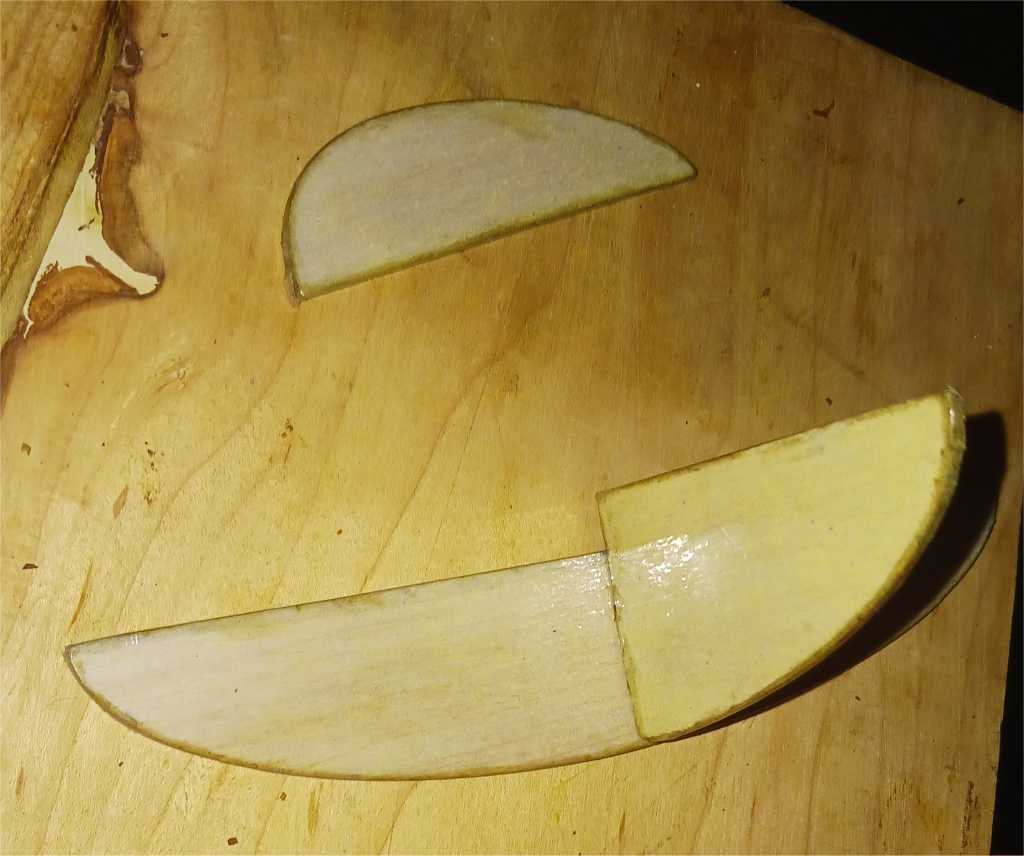
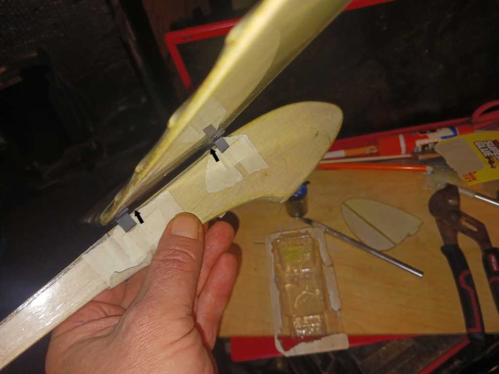
Epoxy the horizontal stabilizer onto the fuselage, it’s easier to do so prior to connecting the elevator sections.
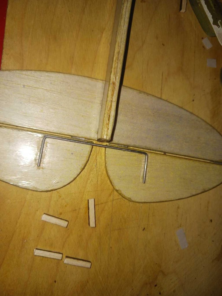
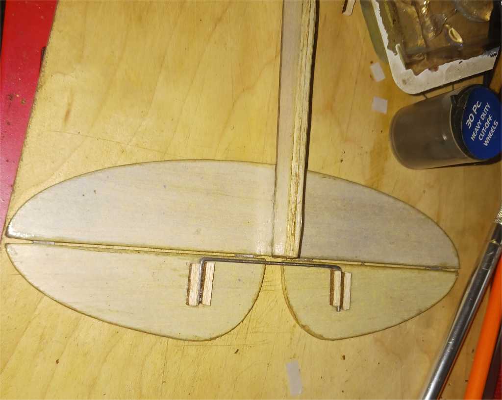
After connecting the stabilizers, it’s helpful to add some joining wire to them so they move as one piece which is necessary for RC control, otherwise skip this step for free flight only control or add later if you change your mind. Take note the covering being removed to allow the stock to be glued into place. CA is preferred for this part.
Mount the rudder.
The balance point is 3/4″ – 1″ from the leading edge of the wing, where the upper spar is located, or slightly aft of it. I used two quarters alone and added a penny alternatively for ballast taped to the nose for the first one, it will vary based upon build choices incorporated. Hold up the plane by the wing tips in this area to see where it balances.
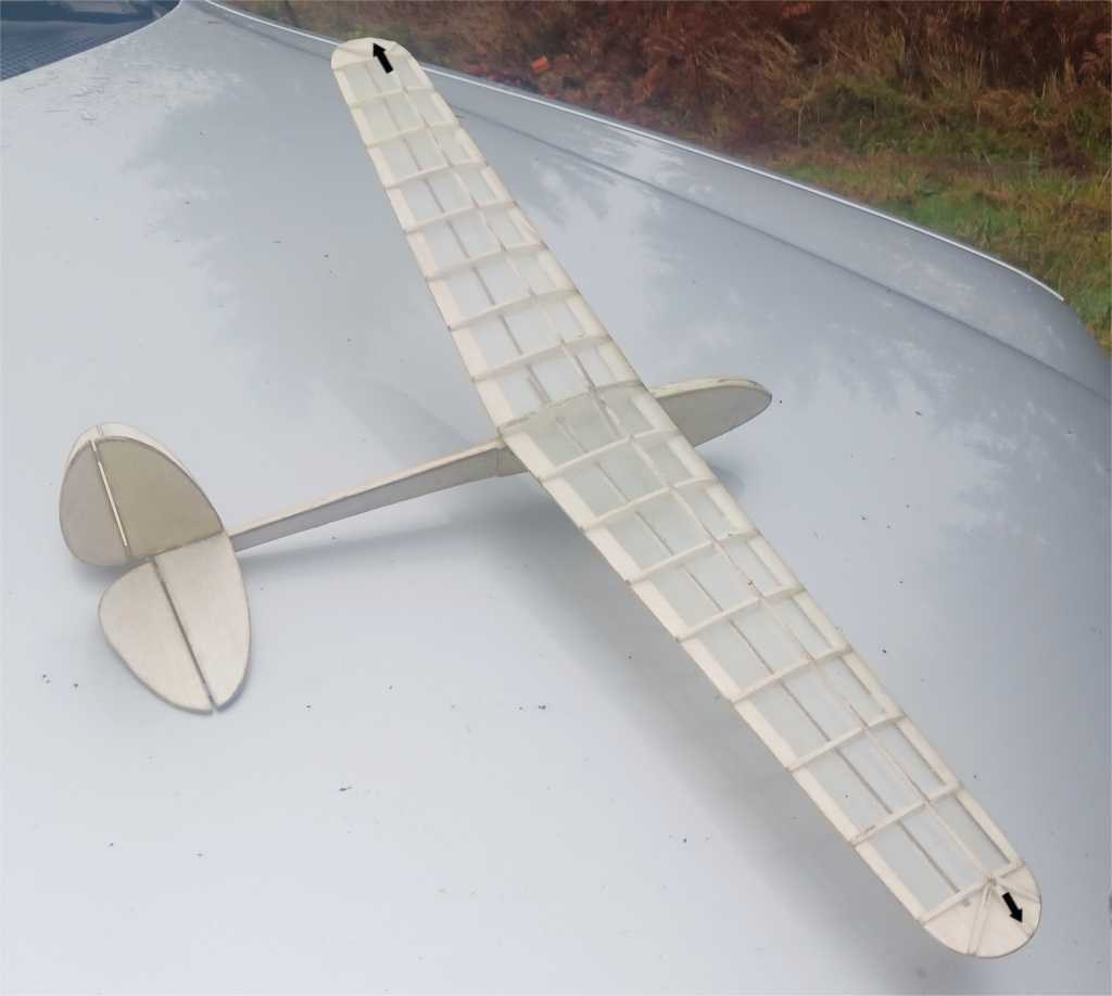
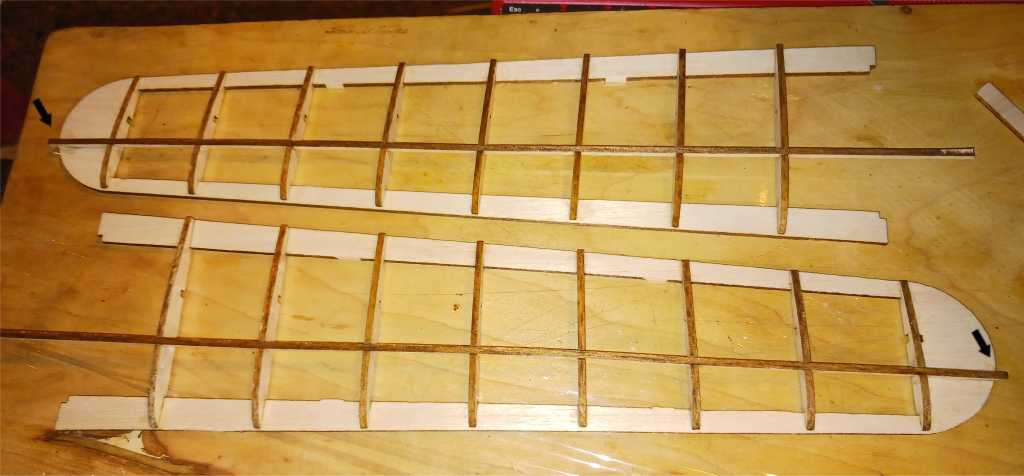
Tape the control surfaces flat or neutral and test glide it. If it veers to the right or left, adjust the angle of the control surface accordingly to counter, with the arrows indicating which direction you position, which will reflect the direction the plane will go.
Once you have achieved smooth, level flight where it glides correctly without pitching in odd directions, you can apply hot glue to the hinge area for a semi-permanent position on the control surfaces or just remain with them taped in place or for RC conversion, remove and take note as to what to trim the plane upon once it’s powered up.
RC conversion instructions will be shared on the next installment.