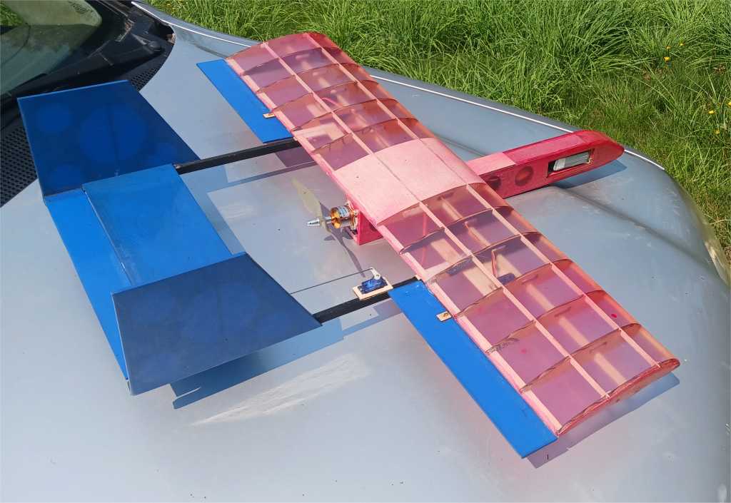
Photo’s and diagrams of the building process beginning with the fuselage.
Parts and side diagram with components mounted:


Connect the fuselage sides prior to beginning construction.
Glue side keel 1/4″ stock, and thin ply front former in place. Wrap around cardboard nose tip and glue in place. Add additional formers. Take note the added sheets between the formers in the aft sections with stock sandwiched between them.

Add some stock inside of the nose section to help upon joining the lower sheeting.

Put some stock, in this case, crumpled packing paper into the void of the nose, foam or other materials can be used, optional. Glue in the second half, side sheeting and glue in the motor mount thin ply stock.


Drill holes in wing mounting balsa stock, and drill holes to feed dowels through the balsa and cardboard stock.
Sand flush.


Wing assembly:
Assemble the wing-plan sheets by cutting along the lines and circles indicating start and end spots to match them.
Glue the end and center balsa ribs to the cardboard versions, pin down the trailing edge and center spar onto the wing-plan. Glue in the ribs accordingly.
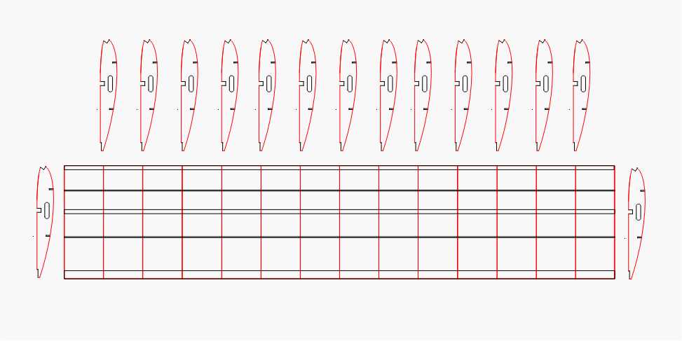
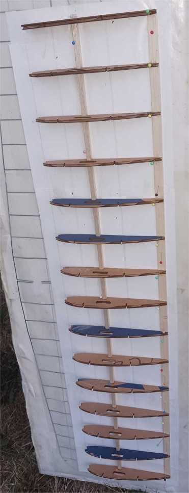
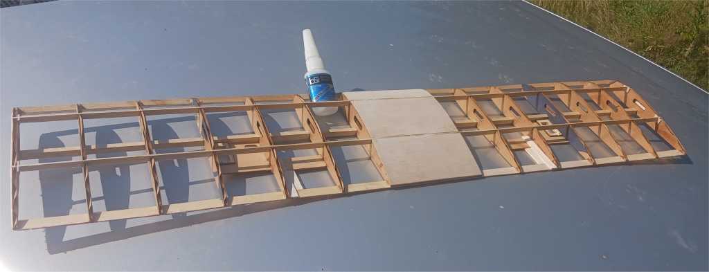
Add leading edge, additional spars, center fuse mounting stock and aileron plate mounting stock.

Shown with boom mounting sections marked out, tissue covered example.
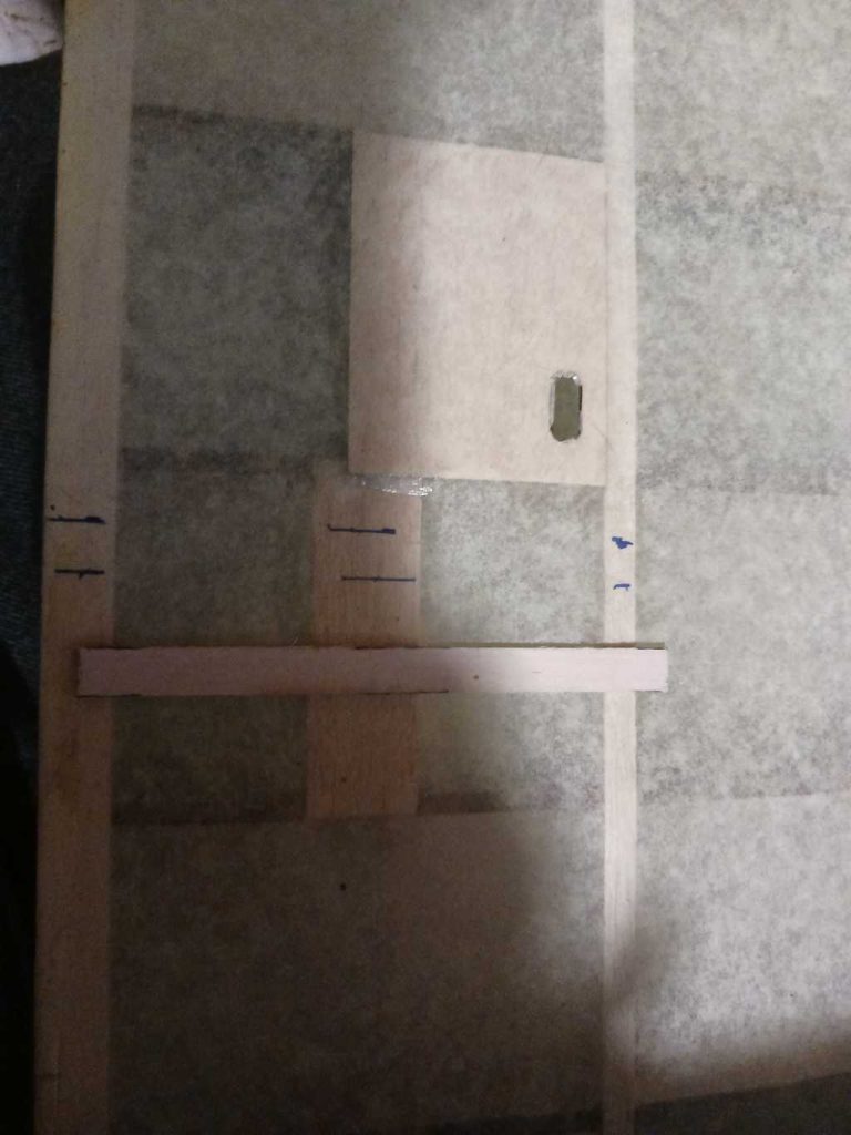
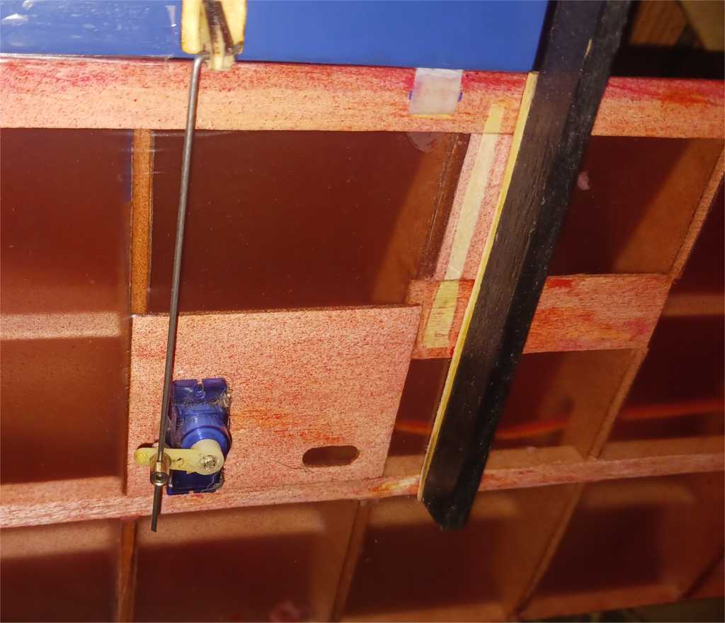
Take note with embedded servo on second photo, now standard format requiring mounting plate thin ply to be installed on top of the sheeting inside of the wing.
Cover the wing and fuselage. Adding center sheeting on the wing is also an option to pursue prior.
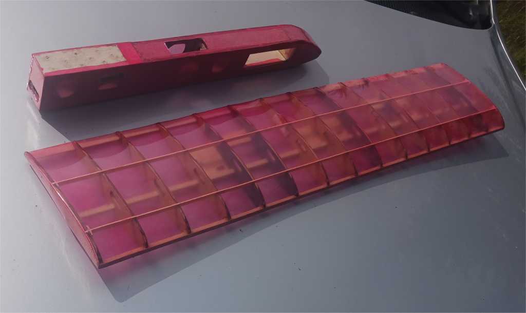
Using quality PVA and CA helps in these and all of the builds. You can also stiffen up the edges of the cardboard by brushing on PVA to their outer areas.
Tail and control surface assembly:
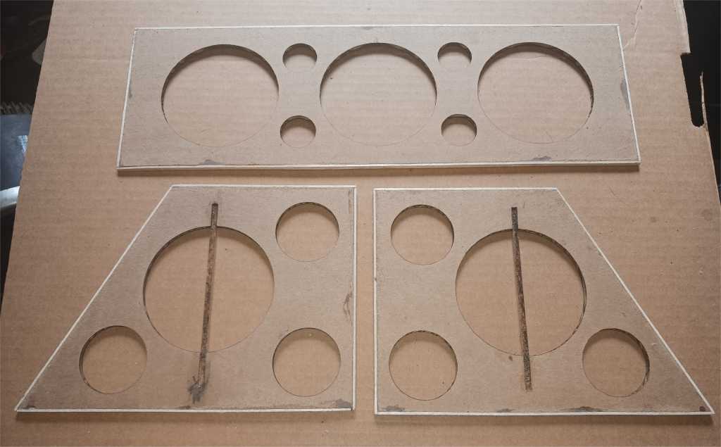
This is pretty straight forward, the sheets are framed out in balsa, covered and mounted, with a strip of support balsa between the tail fin control surfaces. The control surfaces are just sheets of balsa so no need for special instruction upon.
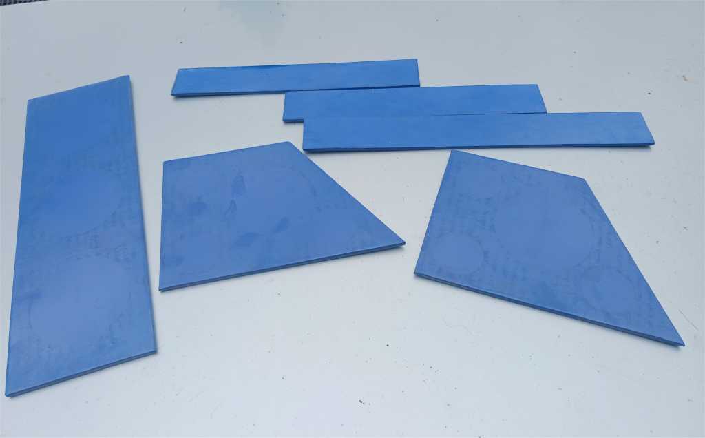
Assembling the air-frame:
The booms are mounted center, and 2 3/4″ from the leading edge of the wing. They extend to the end of the elevator.
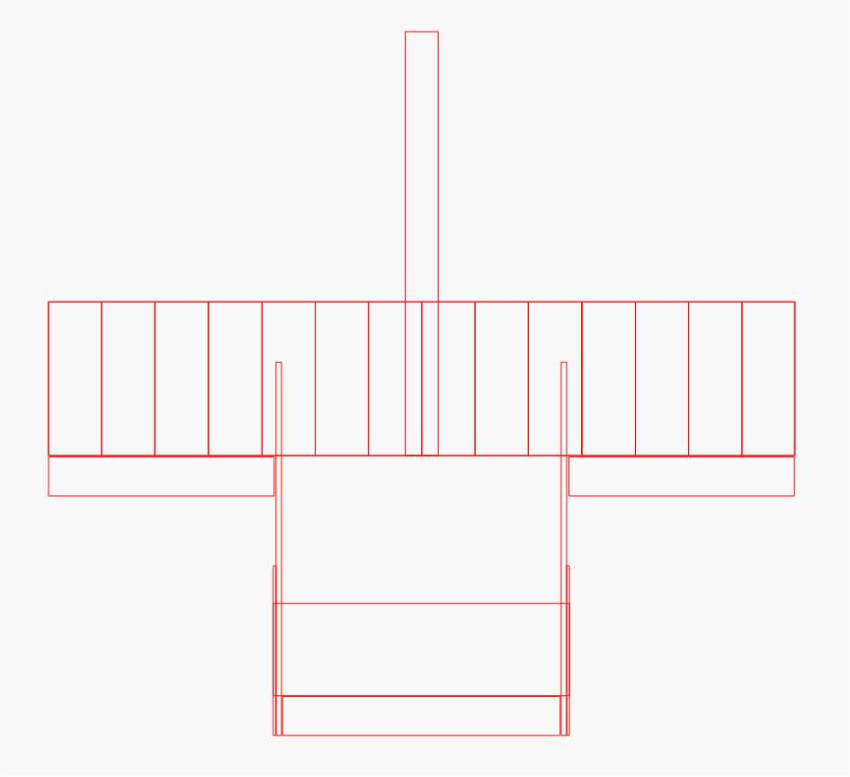
Showing the twin boom connections to the tail areas and wing. Elevator servo mount is positioned in place after it’s two piece assembly is glued together.

Adding the electronics is rather straight forward, no need to elaborate upon that but may later, I certainly am here to help anybody along guiding them along the way in that realm building any of my kits.
The center of gravity is 2 1/2″ from the leading edge of the wing.
This is enough for now for the basic build guide. I will be revising and adding onto it later as necessary and inspired.
